
Multiple electrode vectors for implantable cardiac treatment devices

a cardiac treatment device and multi-electrode technology, applied in the field of multi-electrode vectors for implantable cardiac treatment devices, can solve the problems of inconvenient use, and inability to deliver therapy, and achieve the effect of reducing ambiguity

Inactive Publication Date: 2005-03-03
CAMERON HEALTH
View PDF99 Cites 116 Cited by
  • Summary
  • Abstract
  • Description
  • Claims
  • Application Information

AI Technical Summary

Benefits of technology

"The patent describes an implantable cardiac treatment system that uses electrodes placed in a patient's chest to monitor the heart's activity. The system can select the best sensing vector for detecting and classifying events, and can also analyze multiple vectors simultaneously for added accuracy. This system can prioritize detection and reduce ambiguity by using multiple vectors and checking on each other. The patent also includes operational circuitry and subcutaneous implantable cardiac treatment systems adapted for performing these methods. The technical effects of this patent include improved accuracy and efficiency of implantable cardiac treatment systems."

Problems solved by technology

A problem arises, however, when the cardiac rhythm management device misclassifies an event and, as a result, delivers inappropriate therapy or fails to deliver therapy.
Besides being physically painful to the patient, when a cardiac rhythm management device delivers inappropriate treatment, it can be extremely disconcerting.
Moreover, delivery of an inappropriate therapy can intensify the malignancy of the cardiac arrhythmia or cause an arrhythmia where one was not present.

Method used


Image

  • Multiple electrode vectors for implantable cardiac treatment devices
  • Multiple electrode vectors for implantable cardiac treatment devices
  • Multiple electrode vectors for implantable cardiac treatment devices

Examples


Embodiment Construction

The following detailed description should be read with reference to the Figures, in which like elements in different Figures are numbered identically. The Figures, which are not necessarily to scale, depict selected embodiments and are not intended to limit the scope of the invention. Those skilled in the art will recognize that many of the examples and elements of the examples have suitable alternatives that may be utilized.

The present invention is generally related to cardiac rhythm management devices (e.g., an Implantable Cardioverter / Defibrillator (ICD) system) that provide therapy for patients experiencing particular arrhythmias. The present invention is directed toward sensing architectures for use in cardiac rhythm management devices. In particular, the present invention is suited for ICD systems capable of detecting and defibrillating harmful arrhythmias. Although the sensing architecture is intended primarily for use in an implantable medical device that provides defibri...


PUM


Abstract

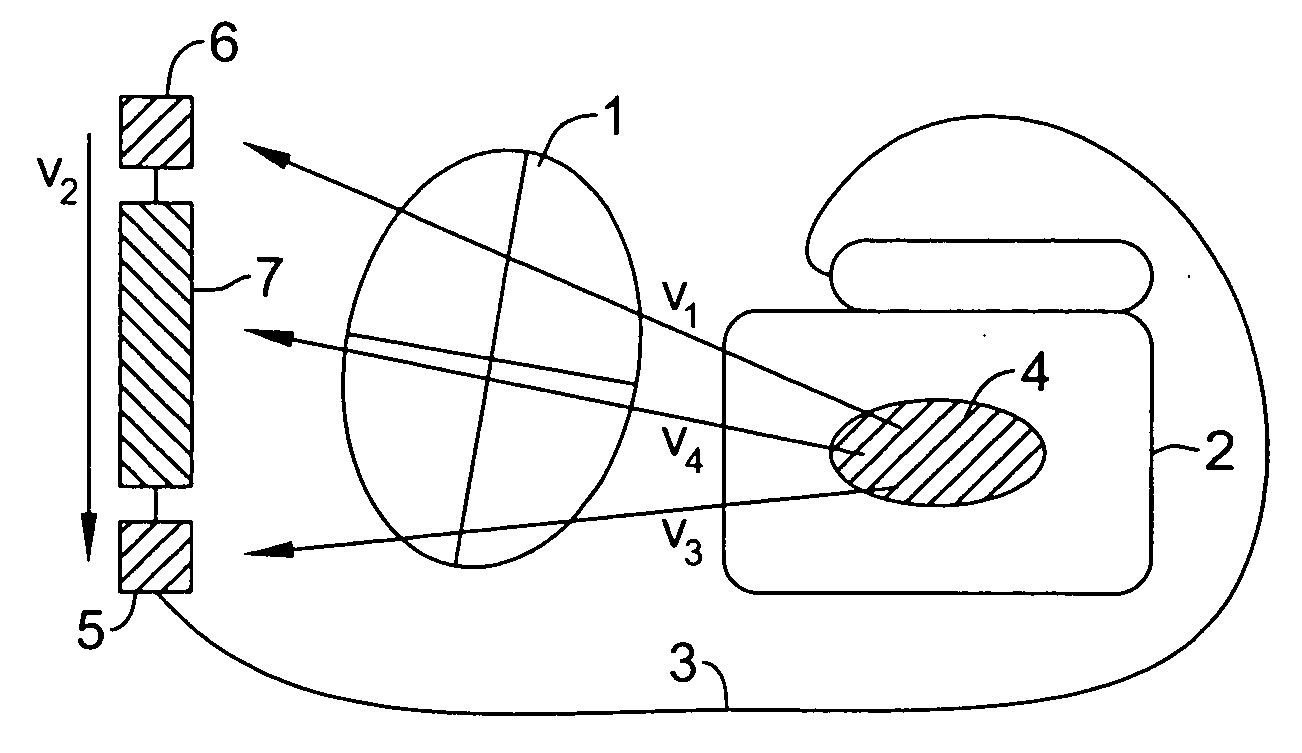
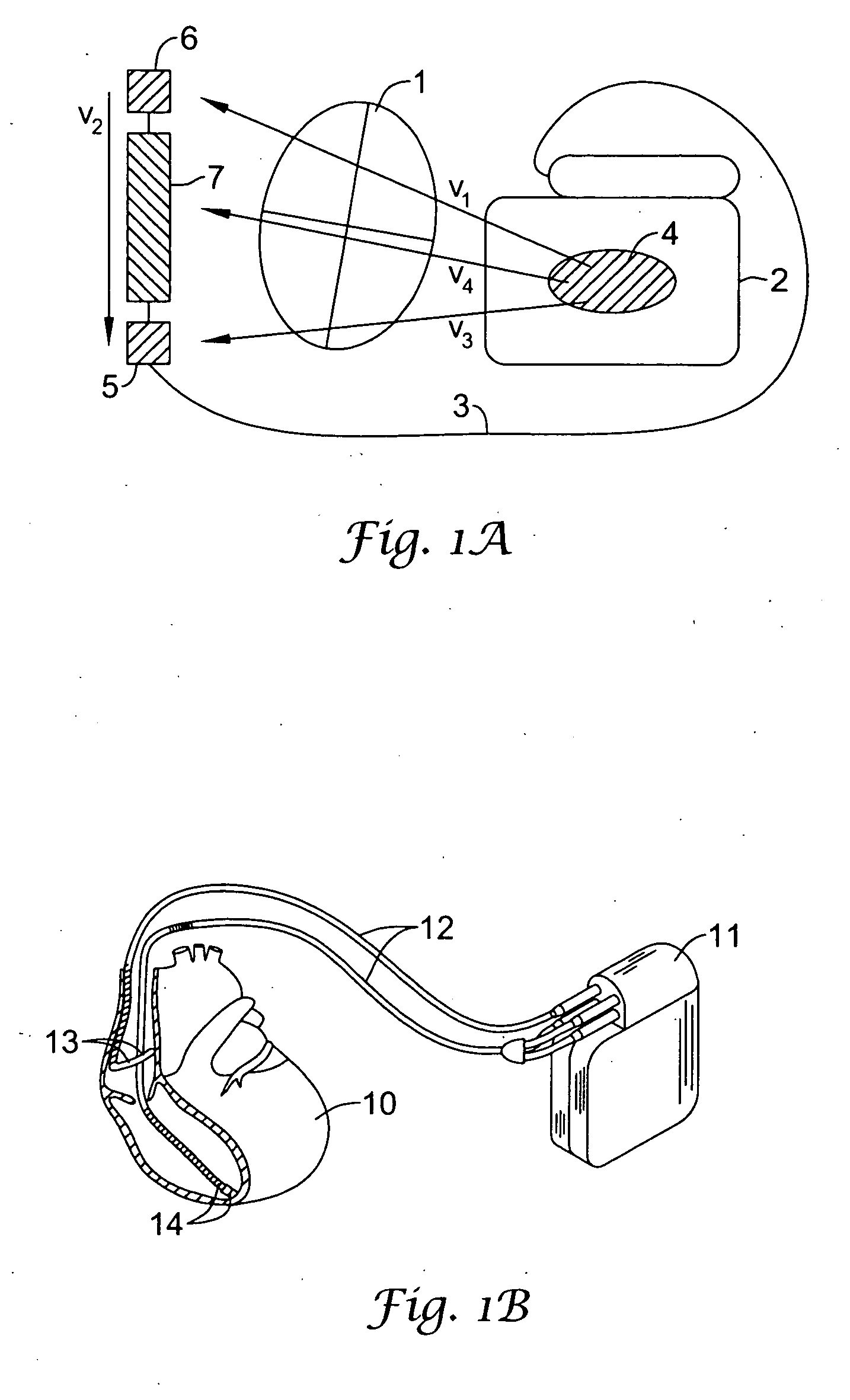
The implantable cardiac treatment system of the present invention is capable of choosing the most appropriate electrode vector to sense within a particular patient. In certain embodiments, the implantable cardiac treatment system determines the most appropriate electrode vector for continuous sensing based on which electrode vector results in the greatest signal amplitude, or some other useful metric such as signal-to-noise ratio (SNR). The electrode vector possessing the highest quality as measured using the metric is then set as the default electrode vector for sensing. Additionally, in certain embodiments of the present invention, a next alternative electrode vector is selected based on being generally orthogonal to the default electrode vector. In yet other embodiments of the present invention, the next alternative electrode vector is selected based on possessing the next highest quality metric after the default electrode vector. In some embodiments, if analysis of the default vector is ambiguous, the next alternative electrode vector is analyzed to reduce ambiguity.

Description

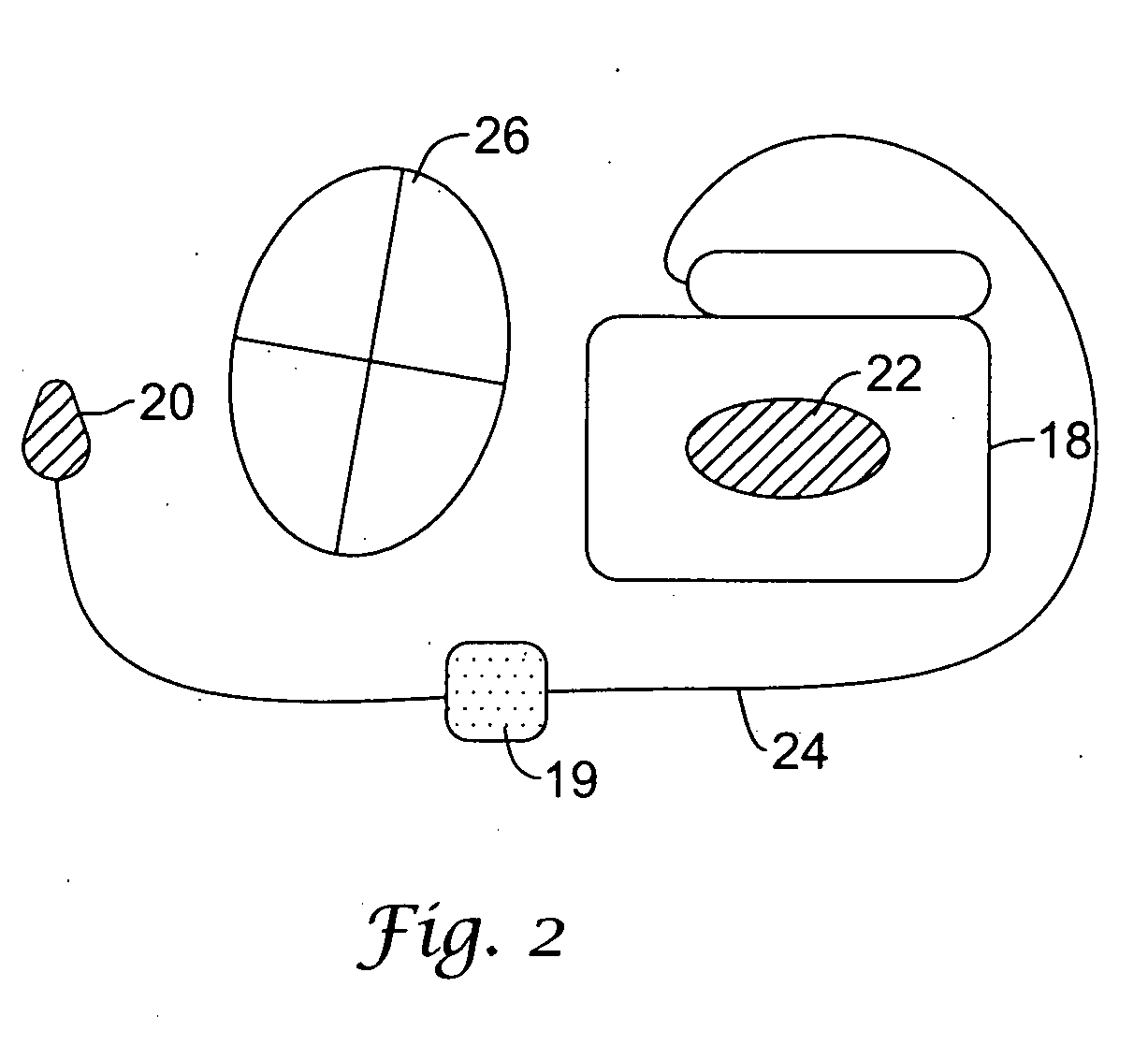
FIELD OF THE INVENTION The present invention relates generally to methods and devices for improving sensing in an implantable cardiac treatment system. More particularly, the present invention relates to the placement of electrodes in an implantable pacing or cardioversion / defibrillation system at defined locations within a patient to create multiple electrode vectors for improved far-field sensing and improved sensing of cardiac events. BACKGROUND Implantable cardiac rhythm management devices are an effective treatment in managing irregular cardiac rhythms in particular patients. Implantable cardiac rhythm management devices are capable of recognizing and treating arrhythmias with a variety of therapies. These therapies include anti-bradycardia pacing for treating bradycardia, anti-tachycardia pacing or cardioversion pulsing for treating ventricular tachycardia, and high energy shocking for treating ventricular fibrillation. Usually, the cardiac rhythm management device delivers ...

Claims


Application Information

Patent Timeline
Patent Type & Authority Applications(United States)
IPC IPC(8): A61B5/361A61B5/024A61B5/07A61B5/276A61B5/308A61N1/362A61N1/368A61N1/39
CPCA61B5/0402A61B5/042A61B5/0424A61B5/7207A61B5/076A61N1/3622A61N1/3925A61B5/04288A61B5/276A61B5/283A61B5/304A61B5/318A61B5/29A61B5/308
Inventor WARREN, JAY A.BARDY, GUST H.
Owner CAMERON HEALTH
Learn More