
Shoulder Positioning fixture, trials and associated method

a technology for positioning fixtures and shoulder blades, applied in the field of orthopaedics, can solve the problems of suboptimal positioning of prostheses, time-consuming process, and difficult positioning of prostheses in the humerus, and achieve the effect of simple bone fixation, quick drilling, and simple fixation to the bon

Inactive Publication Date: 2005-03-03
DEPUY PROD INC
View PDF20 Cites 22 Cited by
  • Summary
  • Abstract
  • Description
  • Claims
  • Application Information

AI Technical Summary

Benefits of technology

[0018] Another technical advantage of the present invention includes the ability of the fixture to remain attached to the bone when the prosthesis is adjusted for version and height. For example, according to one aspect of the present invention, a feature is placed on the periphery of the stem of the trial to cooperate with a feature of the fixture that extends through the cortical wall of the bone. Thus, the present invention provides for the ability to adjust the prosthesis for version and height relative to the bone while the fixture remains attached to the bone.
[0019] Yet another technical advantage of the present invention includes the ability of the fixture of the present invention to provide a simple fixation to the bone. For example, according to one aspect of the present invention, k wires are slideably fitted through the fixture and are secured directly to the bone. Thus, the present invention provides for a simple fixation to the bone. The k wires can be quickly drilled and left in position in the bone until the locking screws are engaged. Preferably the K-wires are removed prior to trial reduction to assist in the insertion of the stem and to optimize the range of motion.
[0020] Another technical advantage of the present invention includes a fixation to the bone that is simple, non-invasive to the bone and easy to remove. For example, according to one aspect of the present invention a clamp in the form of, for example, a set screw is threadably secured to the fixture and is directly in contact with the periphery of the bone. Thus, the present invention provides for a simple, noninvasive fixation to the bone.
[0021] A further technical advantage of the present invention includes the simple, inexpensive and easy to use nature of the fixture of the present invention. For example, according to one aspect of the present invention, the fixture is in the form of a ring with pins to pass through the cortical wall of the bone and to directly engage in grooves in the distal portion of the stem of the trial. The fixture, thus, is small, in the form of a ring and pins, inexpensive, in the form of a simple, inexpensive ring and a simple, inexpensive pin and is easy to use. It slides over the bone and the pins are engaged directly into the bone.
[0022] Yet another technical advantage of the present invention includes the use of a simple guide for drilling holes in the long bone. For example, according to one aspect of the present invention, a guide in the form of a bushing with a handle extending from the bushing is used to slideably fit in the threaded holes of the ring. This guide provides for simple and time saving guiding of the drill for drilling the holes through the cortical bone of the long bone.
[0023] Yet another technical advantage of the present invention includes the ability of the fixture to be used with the implant and to position the implant in the prosthesis during the cementing process. For example, according to one aspect of the present invention, the pins used to position the prosthesis in the bone includes pins that extend from the fixture inwardly toward the prosthesis and that are made of a humanly compatible material or a resorbable material. The pins may be severed from the fixture after the cementing process and remain in the patient. Thus, the present invention provides for the use of a fixture to center the prosthesis during this cementing process.

Problems solved by technology

However, when reconstructing damaged joints when the proximal position of the proximal humerus is severely damaged, the positioning of the prosthetic stem in the humerus is much more difficult.
Such a process is time consuming at best and may often lead to suboptimal positioning of the prosthesis.
These devices have been large and cumbersome and because of their size have not permitted a full range of motion during the trial.

Method used


Image

  • Shoulder Positioning fixture, trials and associated method
  • Shoulder Positioning fixture, trials and associated method
  • Shoulder Positioning fixture, trials and associated method

Examples


Embodiment Construction

[0077] Embodiments of the present invention and the advantages thereof are best understood by referring to the following descriptions and drawings, wherein like numerals are used for like and corresponding parts of the drawings.

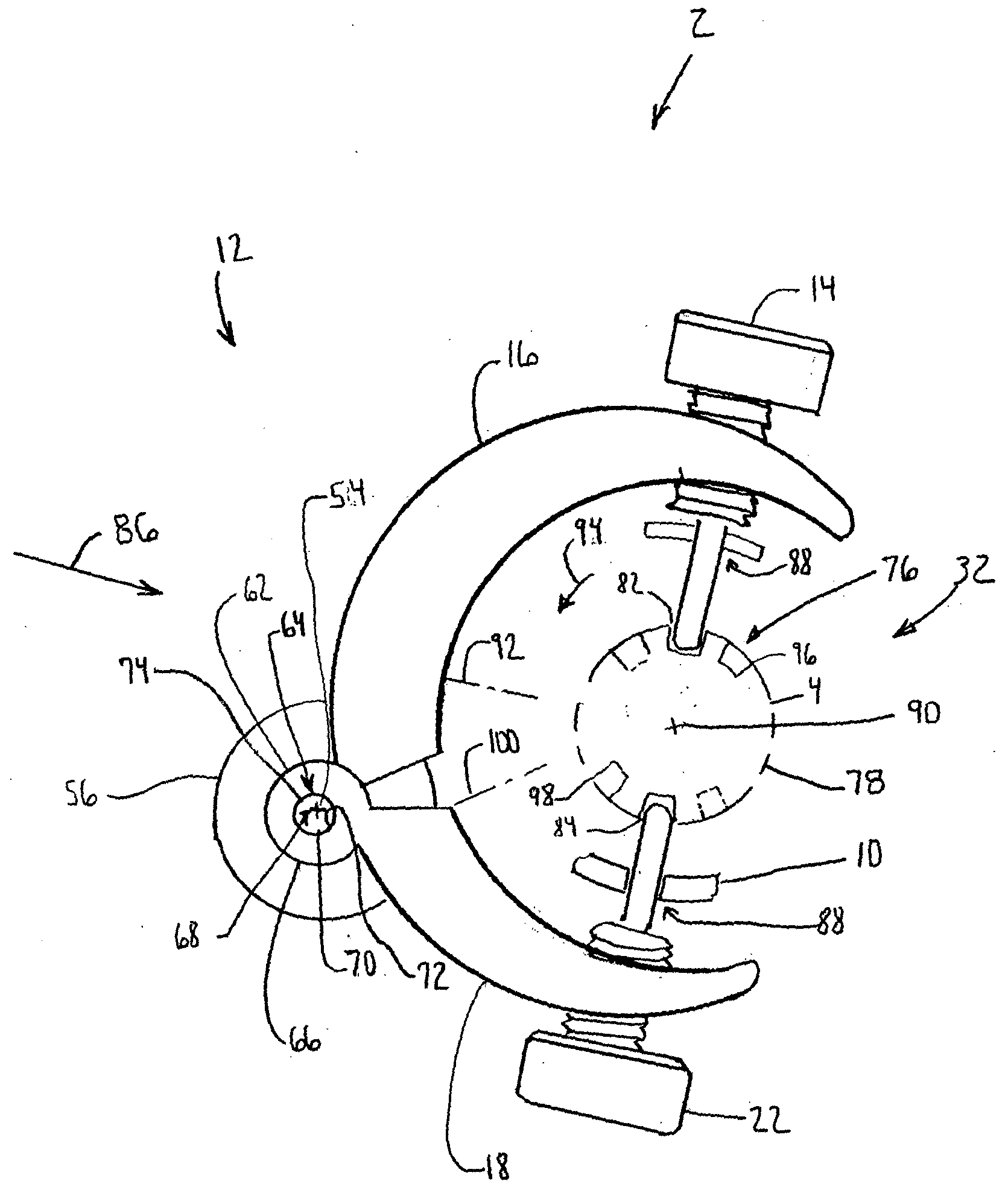
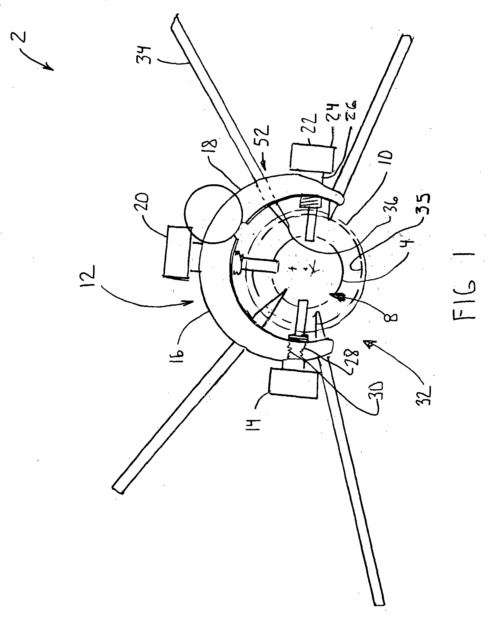
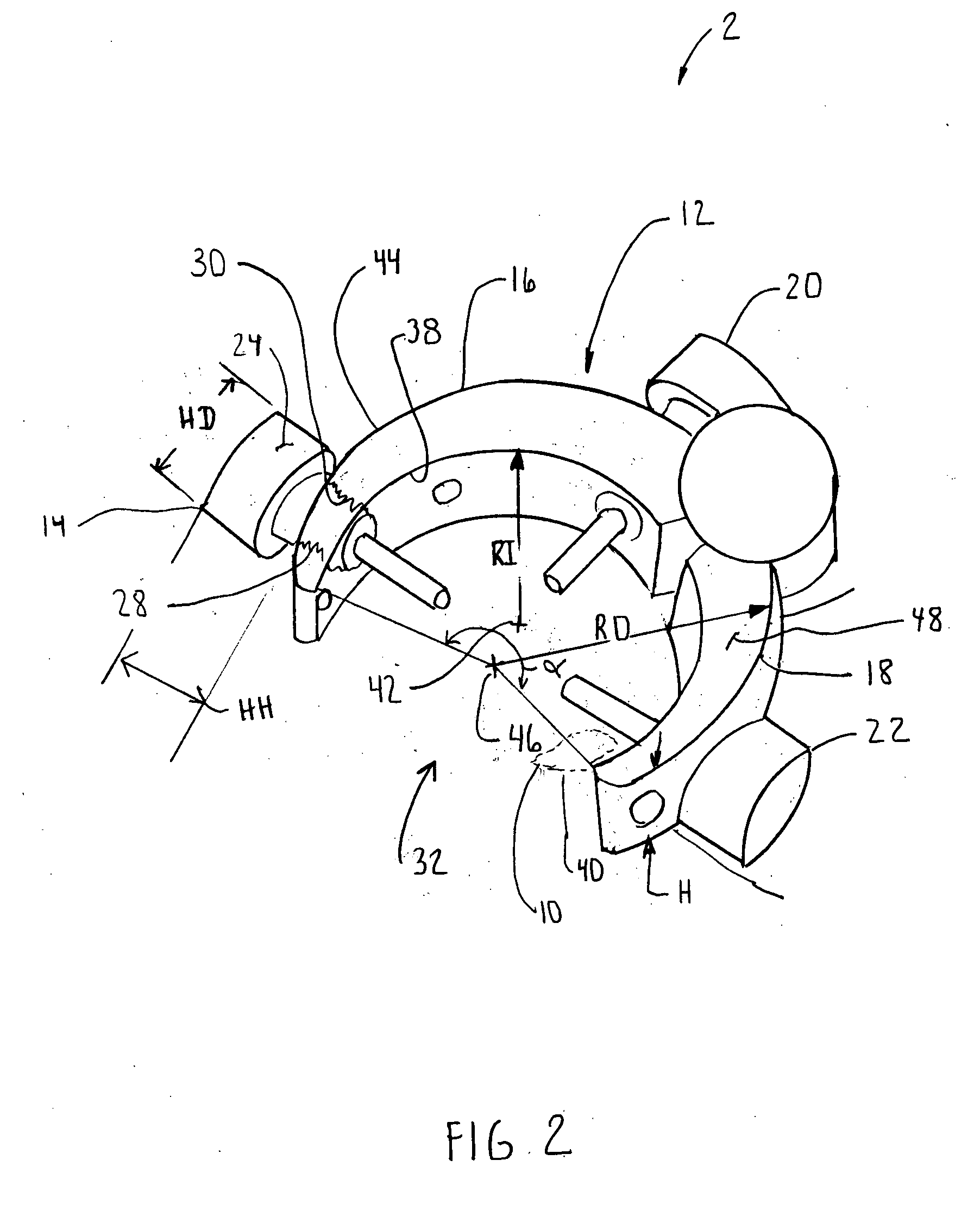
[0078] According to the present invention and referring now to FIG. 1, a positioning fixture 2 is shown for positioning either the trial 4 or the prosthesis 6 (see FIG. 10) in the medullary canal 8 of a long bone 10. The positioning fixture 2 includes a body 12 and a member 14 for cooperation with the body 12. The member 14 extends from the body 12 through a portion of the long bone 10 and into the medullary canal 8. The member 14 may support the trial 4 or the prosthesis 6 as the trial 4 or the prosthesis 6 is positioned with respect to the long bone 10.

[0079] The member 14 may be adapted to permit relative motion between the body 12 and the either the trial 4 or the prosthesis 6 as the trial 4 or the prosthesis 6 cooperates with the member 14.

[0080] The ...


PUM


Abstract

A positioning fixture for positioning at least one of a trial and a prosthesis in the medullary canal of a long bone is provided. The fixture includes a body and a member for cooperation with the body. The member extends from the body through at least a portion of the long bone and into the medullary canal. The member is adapted to support at least one of the trial and the prosthesis as the one of the trial and the prosthesis is positioned with respect to the long bone.

Description

TECHNICAL FIELD OF THE INVENTION [0001] The present invention relates generally to the field of orthopaedics, and more particularly, to an instrument for use in arthroplasty. BACKGROUND OF THE INVENTION [0002] The present invention relates to implantable articles and methods of for implanting such articles. More particularly the invention relates to a bone prosthesis, prosthesis trial, instrument and method for implanting the same. [0003] There are known to exist many designs for and methods for implanting implantable articles, such as bone prostheses. Such bone prostheses include components of artificial joints, such as elbows, hips, knees and shoulders. [0004] One such implantable prosthesis is a shoulder prosthesis. During the life time of a patient, it may be necessary to perform a total shoulder replacement procedure on a patient as a result of, for example, disease or trauma, for example disease from osteoarthritis or rheumatoid arthritis. Currently, most implantable shoulder ...

Claims


Application Information

Patent Timeline
Patent Type & Authority Applications(United States)
IPC IPC(8): A61B17/17A61F2/00A61F2/02A61F2/30A61F2/40A61F2/46
CPCA61F2/4059A61B2017/1778A61F2/4684A61F2002/30131A61F2002/302A61F2002/30428A61F2002/30471A61F2002/30476A61F2002/305A61F2002/30507A61F2002/30537A61F2002/30581A61F2002/30827A61F2220/0025A61F2220/0091A61F2230/0013A61F2230/0065A61F2250/0004A61F2310/00011A61F2/4612A61B17/1778
Inventor ONDRLA, JEFFREY M.HAHN, ANDREA L.
Owner DEPUY PROD INC
Learn More