
Cyclone separating apparatus and vacuum cleaner having the same

a technology of cyclone separation and vacuum cleaner, which is applied in the direction of vortex flow apparatus, cleaning filter means, separation processes, etc., can solve the problems of inconvenience for users to operate, deterioration of suction operation and cleaning efficiency, and inconvenient operation of users, so as to prevent deterioration of suction force and increase dust collection efficiency

Inactive Publication Date: 2005-03-10
SAMSUNG GWANGJU ELECTRONICS CO LTD
View PDF19 Cites 46 Cited by
  • Summary
  • Abstract
  • Description
  • Claims
  • Application Information

AI Technical Summary

Benefits of technology

[0007] The present invention has been developed in order to solve the above drawbacks and other problems associated with the conventional arrangement. An object of the present invention is to provide a cyclone separating apparatus of a compact structure, and a vacuum cleaner having the same, which is capable of increasing dust-collecting efficiency in a plurality of the cyclone dust-collecting apparatuses, and also preventing deterioration of a suction force.

Problems solved by technology

The conventional cyclone separating apparatuses, however, have the following problems.
First, the structure where the first cyclone is connected to the auxiliary cyclone is complicated, and the suction force generated from the main body of the vacuum cleaner is hard to deliver, thus causing the suction operation and cleaning efficiency to deteriorate.
Secondly, since the arrangement of the first cyclone and the auxiliary cyclone is not compact, the cyclone separating apparatus indispensably requires to be large enough to adequately perform the dust-collecting operation.
Accordingly, the vacuum cleaner with such a cyclone separating apparatus is bulky, difficult to maintain and causes an inconvenience to a user to operate.
Thirdly, the conventional cyclone separating apparatuses are problematic in that since a connection path between the first cyclone and the auxiliary cyclone is complicated, a production process is complicated and, therefore, the number of parts and production costs are increased.
Thus, a heretofore unaddressed need exists in the industry to address the aforementioned deficiencies and inadequacies.

Method used


Image

  • Cyclone separating apparatus and vacuum cleaner having the same
  • Cyclone separating apparatus and vacuum cleaner having the same
  • Cyclone separating apparatus and vacuum cleaner having the same

Examples


Embodiment Construction

[0023] Certain embodiments of the present invention will be described in greater detail with reference to the accompanying drawings.

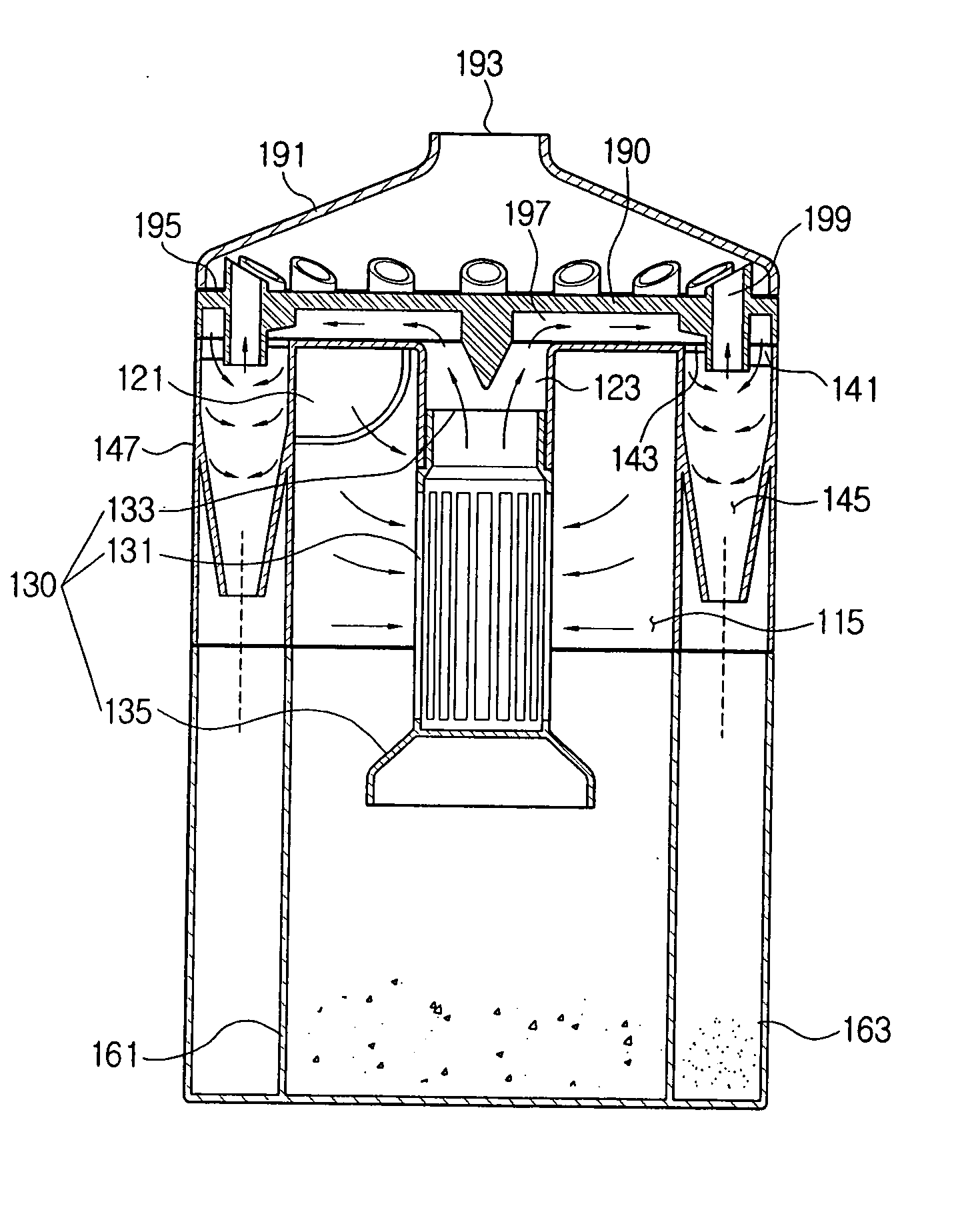
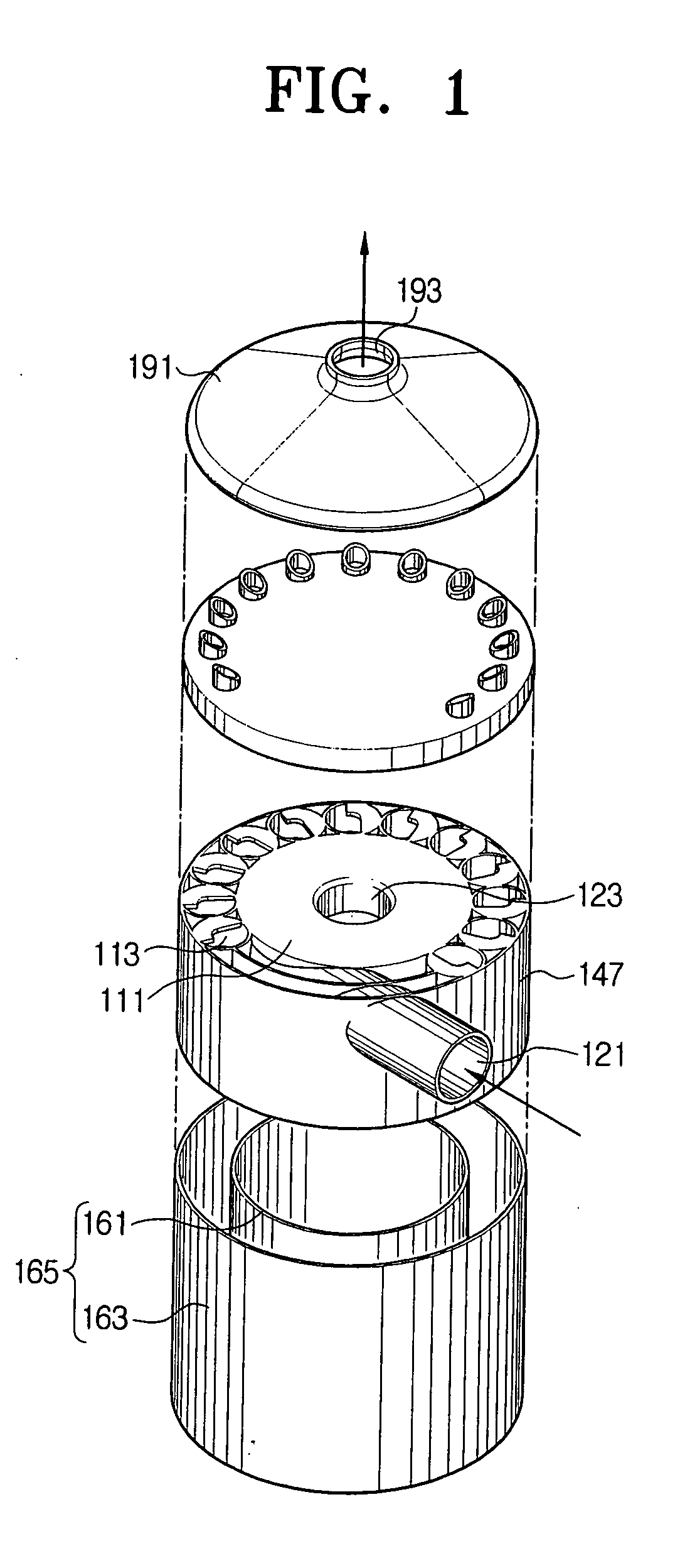
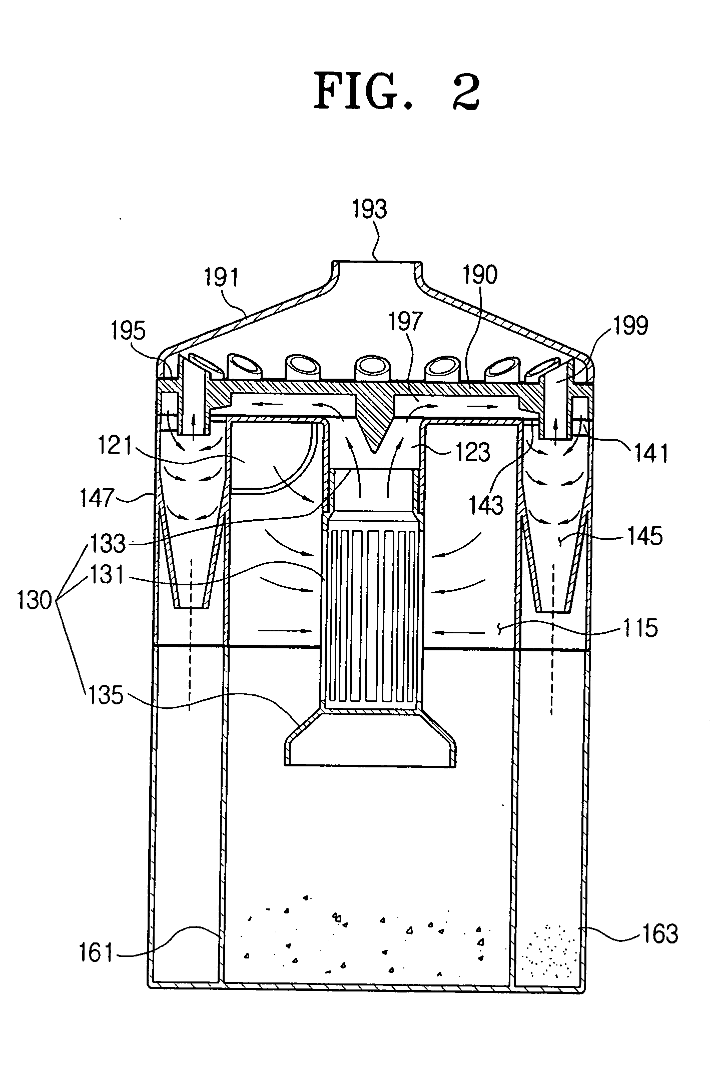
[0024] The cyclone separating apparatus according to a preferred embodiment of the present invention includes a first cyclone 111, a plurality of second cyclones 113, an inlet-outlet cover 190 installed on the upper part of the first cyclone 111 and the second cyclones 113, a cyclone cover 191, and a dust-collecting unit 165. A plurality of the second cyclones 113 is installed on the outer periphery of the first cyclone 111 enclosing the first cyclone 111. The first cyclone 111, and each of the second cyclones 113 are integrally formed, and a separating partition 250 is installed between the second cyclones 113 (refer to FIG. 3). The presence of the separating partition 250 increases the firmness of the cyclone separating apparatus 100 because the separating partition 250 partitions each of the second cyclones 113.

[0025] A chamber wall 147 is formed i...


PUM

PropertyMeasurementUnit
centrifugal forceaaaaaaaaaa
cylindrical shapeaaaaaaaaaa
conical shapeaaaaaaaaaa

Abstract

Disclosed is a cyclone separating apparatus and a vacuum cleaner having the same. The cyclone separating apparatus includes a first cyclone for separating dust-ladened air, a plurality of second cyclones for separating fine dust particles via a second separation of dust using centrifugal force from air which was previously separated at the first cyclone, and an inlet-outlet cover installed on the upper part of the first cyclone and the second cyclones. The inlet-outlet cover allows fluid-communication between the first cyclone and the second cyclones, and discharge of dust-removed air from the second cyclone. Because the plurality of cyclones separates dust utilizing a compact structure, suction force deterioration is prevented and dust-collecting efficiency is increased.

Description

REFERENCE TO RELATED APPLICATION [0001] This application claims priority under 35 U.S.C. § 119 to Korean Patent Application No. 2003-63211, filed on Sep. 9, 2003, the entire content of which is incorporated herein by reference. CROSS-REFERENCE TO RELATED APPLICATIONS [0002] This application is related to copending applications entitled “Cyclone Dust Separating Apparatus and Vacuum Cleaner having the same” (Korean Application No. 2003-63212, filed Sep. 9, 2003), “Cyclone Separating Apparatus and Vacuum Cleaner Equipped with the same” (Korean Application No 2003-63213, filed Sep. 9, 2003), and “Cyclone Separating Apparatus and Vacuum Cleaner having the same” (Korean Application No. 2003-62520, filed Sep. 8, 2003) whose disclosures are owned by the same assignee as the present application and are entirely incorporated herein by reference.FIELD OF THE INVENTION [0003] The present invention relates to a cyclone separating apparatus and vacuum cleaner having the same, and more particularl...

Claims


Application Information

Patent Timeline
Patent Type & Authority Applications(United States)
IPC IPC(8): A47L9/16B04C5/06B04C5/13B04C5/26
CPCA47L9/1625A47L9/1641Y10S55/03B04C5/13B04C5/26B04C5/06A47L9/16
Inventor OH, JANG-KEUNLEE, HYUN-JU
Owner SAMSUNG GWANGJU ELECTRONICS CO LTD
Features
  • Generate Ideas
  • Intellectual Property
  • Life Sciences
  • Materials
  • Tech Scout
  • Unparalleled Data Quality
  • Higher Quality Content
  • 60% Fewer Hallucinations
Learn More