
High rigid tilt device in a steering column for a vehicle

Inactive Publication Date: 2005-03-10
HYUNDAI MOBIS CO LTD
View PDF9 Cites 20 Cited by
  • Summary
  • Abstract
  • Description
  • Claims
  • Application Information

AI Technical Summary

Benefits of technology

[0010] The present invention has been made to solve the foregoing problems and it is therefore an object of the present invention to provide a tilt device which can impart a high supporting strength to a steering column while reliably locking the same.
[0012] It is still another object of the invention to enable the main bracket to be fabricated through casting. As the main bracket can be fabricated through casting, there are advantages that the main bracket can be precisely fabricated into a complicated configuration as well as utilize nonferrous light metal such as Mg and Al (including alloys thereof) which are not readily pressed owing to a problem of tearing.
[0013] It is a further object of the invention to provide a main bracket which is not restricted in thickness. This may have various effects: For example, strength can be enhanced to a desired magnitude and a fabrication method may not be restricted.
[0014] It is a still further object of the invention to provide a main bracket which can be made of various materials such as Al, Mg and composite. As a result, the bracket can be reduced in weight, and a most suitable material can be used according to the environment of a vehicle.
[0017] In the afore described invention, the tilt device can enhance the supporting strength of the steering column via the supporting portion of the main bracket and the tilt plate can be efficiently deformed to reliably lock the tilt of the steering column.

Problems solved by technology

As a result, there is a problem that the steering column has a weak supporting strength, in particular, in lateral directions.
However, the above structure has a problem that fabrication is not simple since the steering bracket 1 has a complicated configuration.
As a result, during locking, the right side wall 4 is not uniformly deformed across its front and rear portions thereby obstructing reliable locking.

Method used


Image

  • High rigid tilt device in a steering column for a vehicle
  • High rigid tilt device in a steering column for a vehicle
  • High rigid tilt device in a steering column for a vehicle

Examples


Embodiment Construction

[0023] The following detailed description will present a preferred embodiment of the invention in reference to the accompanying drawings.

[0024] First of all, in a tilt device in a steering column, the present invention may use any components as long as they conform to the object of the invention except for a mounting bracket and a tilt bracket corresponding to a main bracket and a tilt plate of the present invention.

[0025] For example, other components of a conventional tilt device except for the mounting bracket and the tilt bracket can be coupled with the main bracket and the tilt plate of the invention to constitute the tilt device of the invention.

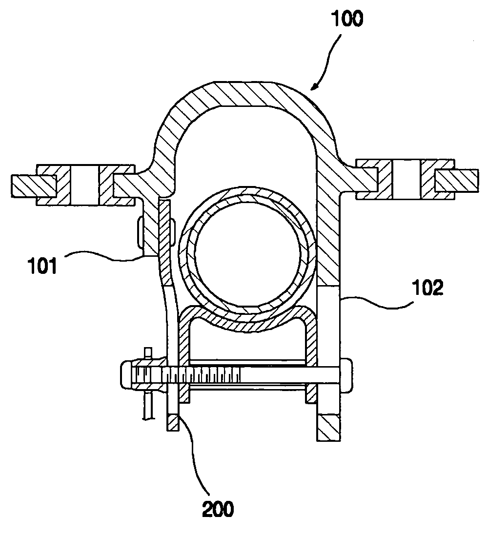
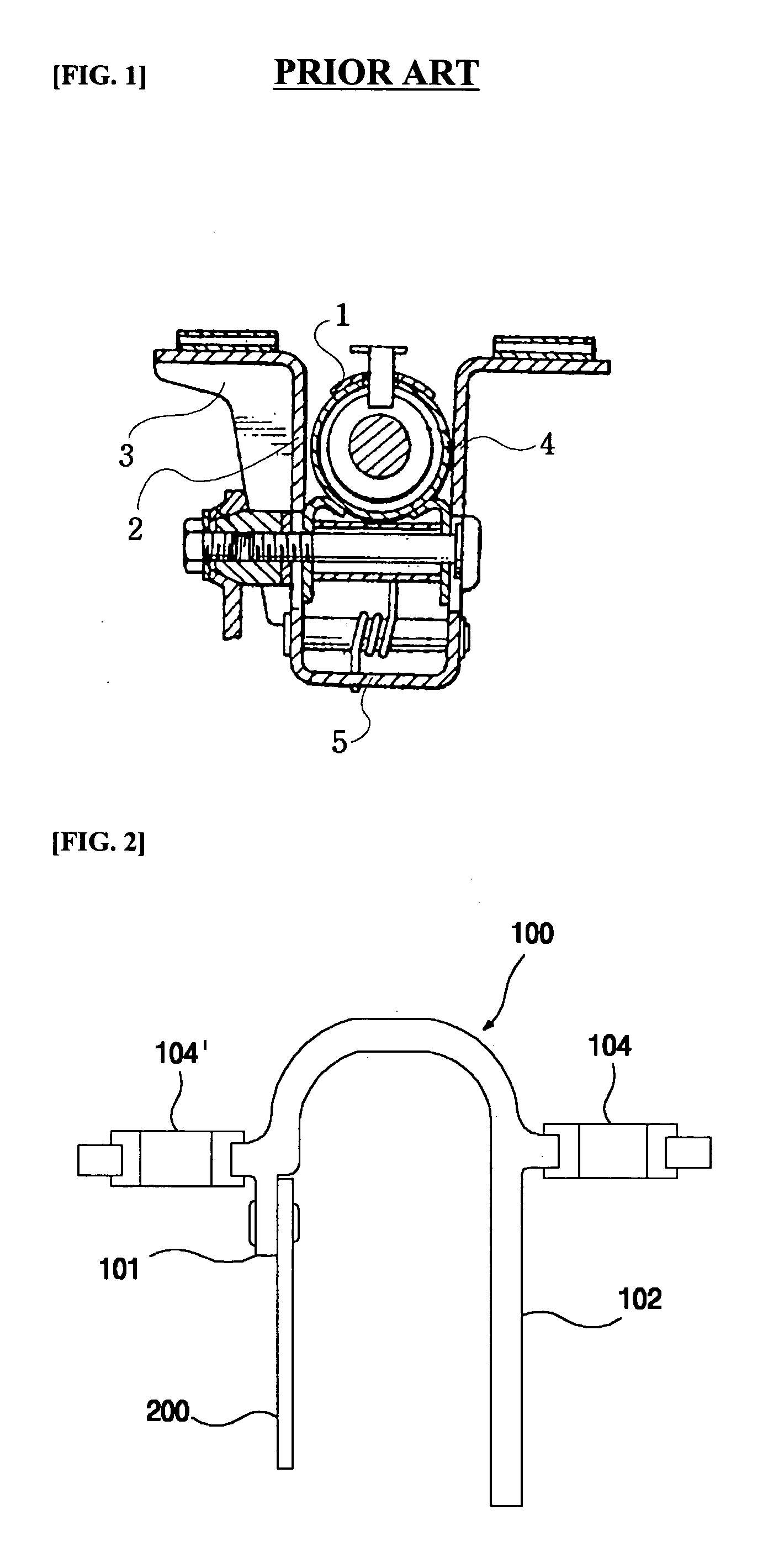
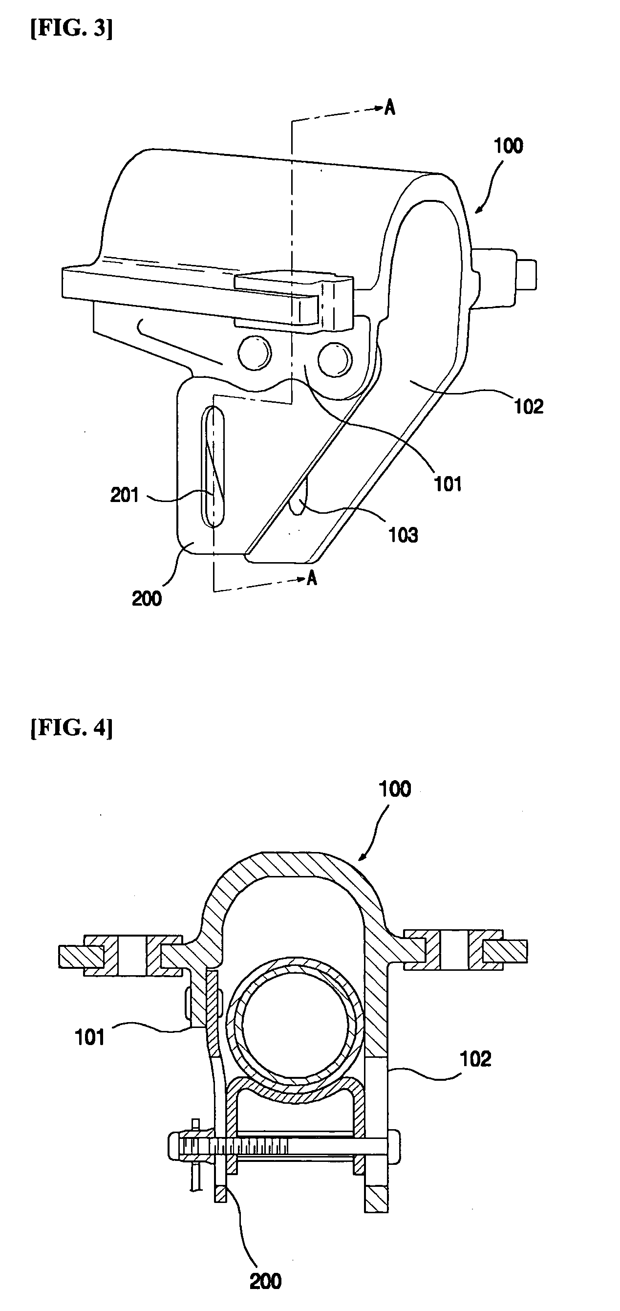
[0026]FIGS. 2 and 3 illustrate a main bracket 100 and a tilt plate 200 according to an embodiment of the invention. As shown in FIGS. 2 and 3, the main bracket 100 has a coupling portion 101 in the left to be coupled with the tilt plate 200 and a supporting portion 102 in the right. The coupling portion 101 is preferably formed shor...


PUM


Abstract

The present invention relates to a tilt device for allowing a steering column to be tilted so that a driver can adjust the position of a steering wheel to conform to his / her figure in order to more comfortably drive a vehicle. The tilt device of the invention has an effect in that it can impart a high supporting strength to the steering column while reliably locking the same.

Description

[0001] The present disclosure relates to subject matter contained in priority Korean Application No. 10-2003-0062326, filed on Sep. 6, 2003, which is herein expressly incorporated by reference in its entirety. BACKGROUND OF THE INVENTION [0002] 1. Field of the Invention [0003] The present invention relates to a tilt device for allowing a steering column to be tilted so that a driver can adjust the position of a steering wheel to conform to his / her figure in order to more comfortably drive a vehicle. [0004] 2. Background of the Related Art [0005] In general, a tilt device comprises a mounting bracket fixed to a vehicle body, a tilt bracket connected to the mounting bracket and having a pair of side walls with tilt slots for guiding a tilt operation, a distance bracket fixed from below to the outer periphery of a steering tube which rotatably supports a steering shaft and having a pair of side walls with through holes, and a tilt-locking mechanism arranged through the tilt slots of th...

Claims


Application Information

Patent Timeline
IPC IPC(8): B62D1/184B62D1/18B62D1/187
CPCB62D1/184B62D1/18
Inventor LEE, BYEONG-HOON
Owner HYUNDAI MOBIS CO LTD
Learn More