Electrostatic precipitators with insulated driver electrodes

a technology of driver electrodes and electrostatic precipitators, which is applied in electrostatic separation, solid separation, chemical apparatuses and processes, etc., can solve the problems of limited voltage difference, undesirable in excess quantities, and reduce the collecting so as to reduce the collection efficiency of the system, the voltage difference can be increased, and the particle collection efficiency.

Inactive Publication Date: 2005-03-10
THE SHARPER IMAGE
View PDF98 Cites 85 Cited by
  • Summary
  • Abstract
  • Description
  • Claims
  • Application Information

AI Technical Summary

Benefits of technology

[0009] The insulation (i.e., dielectric material) on the driver electrodes allows the voltage potential to be increased between the driver and collector electrodes, to a voltage potential that would otherwise cause arcing if the insulation were not present. This increased voltage potential increases particle collection efficiency. Additionally, the insulation will reduce, and likely prevent, any arcing from occurring, especially if a carbon path is formed between the collector and driver electrodes, e.g., due to an insect getting caught therebetween.

Problems solved by technology

Further, the corona discharge produced by the electrode 102 can release ozone into the ambient environment, which can eliminate odors that are entrained in the airflow, but is generally undesirable in excess quantities.
However, the extent that the voltage difference can be increased is limited because arcing will eventually occur between the collector electrodes 104 and the driver electrodes 106.
Such arcing will typically decrease the collecting efficiency of the system.

Method used


Image

  • Electrostatic precipitators with insulated driver electrodes
  • Electrostatic precipitators with insulated driver electrodes
  • Electrostatic precipitators with insulated driver electrodes

Examples


Embodiment Construction

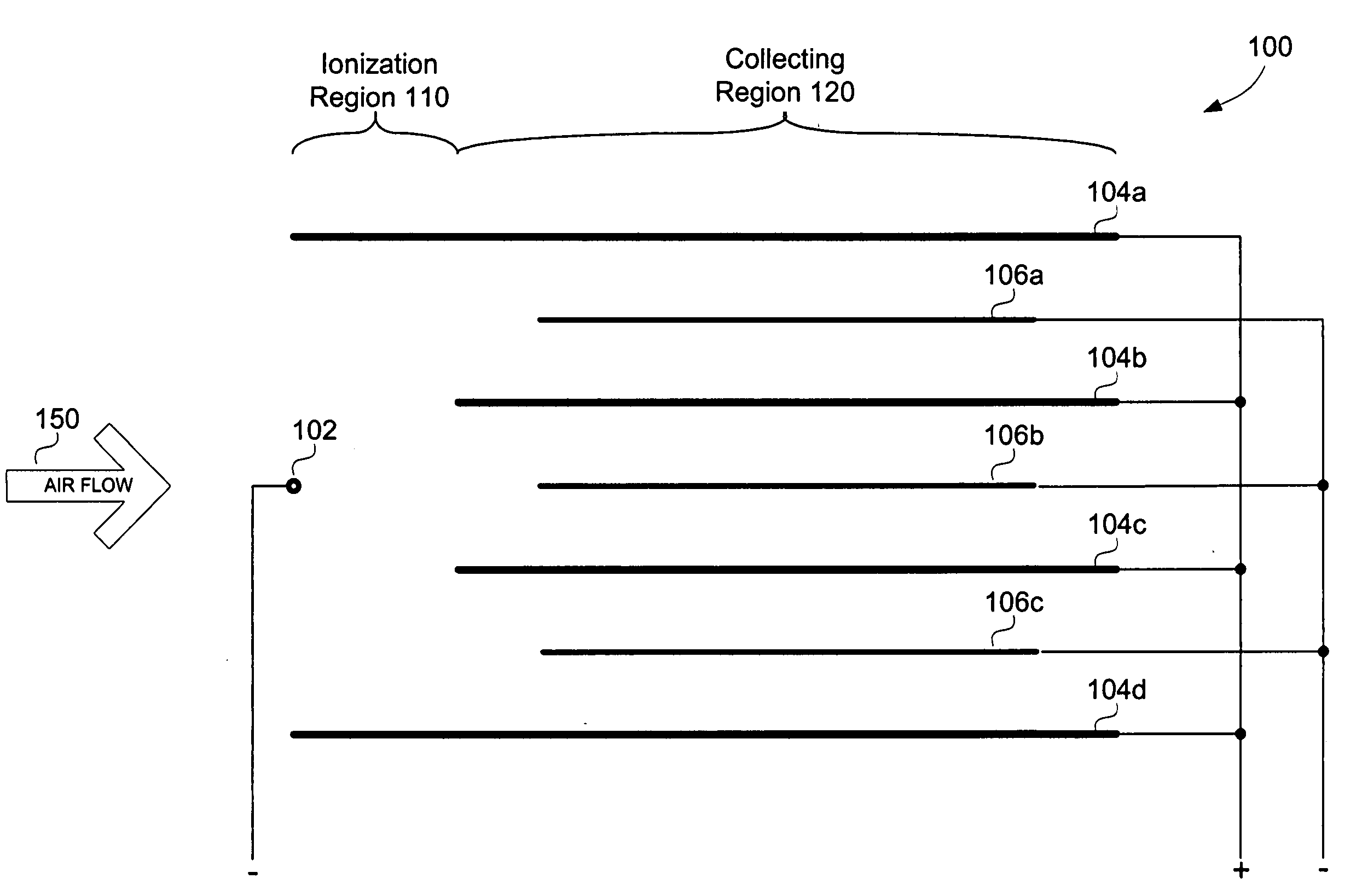
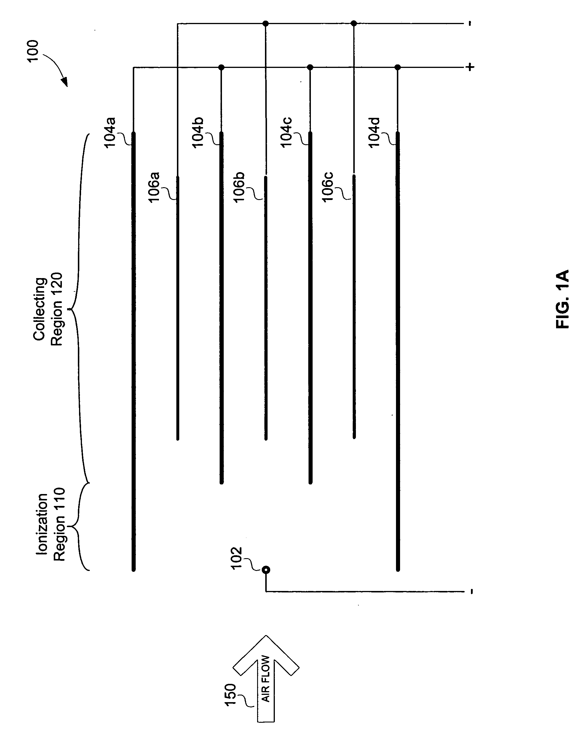
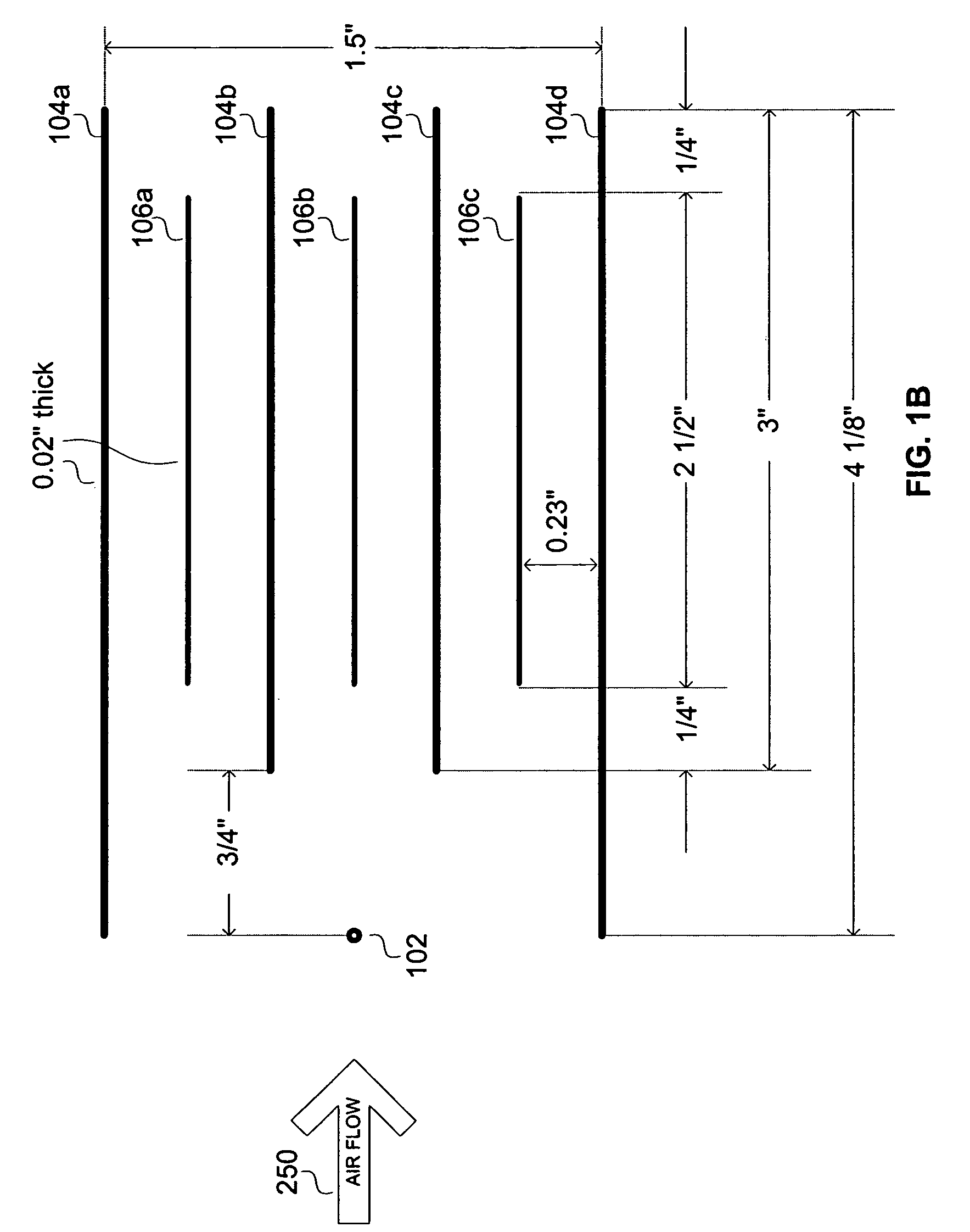
[0034]FIG. 2A illustrates schematically, an ESP module or system 200, according to an embodiment of the present invention. The system 200 includes a corona discharge electrode 202 (also known as an emitter electrode) and a plurality of collector electrodes 204. An insulated driver electrode 206 is located between each pair of collector electrodes. In the embodiment shown there are four collector electrodes 204a, 204b, 204c and 204d, and three driver electrodes 206a, 206b and 206c. In this embodiment, the corona discharge electrode 202 is shown as receiving a negative charge. The collector electrodes 204, which are likely metal plates, are shown as receiving a positive charge. The driver electrodes 206, which are also likely metal plates, are shown as receiving a negative charge. FIG. 2B illustrates exemplary dimensions for the system or module of FIG. 2A. A comparison between FIGS. 1A and 2A reveals that the only difference between the two figures is that the driver electrodes in FI...


PUM


Abstract

Electrostatic precipitator (ESP) systems and methods are provided. A system includes at least one corona discharge electrode and at least one collector (and likely, at least a pair of collector electrodes) that extend downstream from the corona discharge electrode. An insulated driver electrode is located adjacent the collector electrode, and where there is at least a pair of collector electrodes, between each pair of collector electrodes. A high voltage source provides a voltage potential to the at least one of the corona discharge electrode and the collector electrode(s), to thereby provide a potential different therebetween. The insulated driver electrode(s) may or may not be at a same voltage potential as the corona discharge electrode, but should be at a different voltage potential than the collector electrode(s).

Description

PRIORITY CLAIM [0001] The present application is a continuation-in-part of U.S. patent application Ser. No. 10 / 717,420 filed Nov. 19, 2003, entitled “Electro-Kinetic Air Transporter and Conditioner Devices with Insulated Driver Electrodes” (Attorney Docket No. SHPR-01414US1), which claims priority under 35 U.S.C. 119(e) to U.S. Provisional Patent Application No. 60 / 500,437, filed Sep. 5, 2003, entitled “Electro-Kinetic Air Transporter and Conditioner Devices with Insulated Driver Electrodes” (Attorney Docket No. SHPR-01414US0), both of which are incorporated by reference herein, and to both of which the present application claims priority. CROSS-REFERENCE TO RELATED ART [0002] The present invention is related to the following patent application and patent, each of which is incorporated herein by reference: U.S. patent application Ser. No. 10 / 074,207, filed Feb. 12, 2002, entitled “Electro-Kinetic Air Transporter-Conditioner Devices with Interstitial Electrode”; and U.S. Pat. No. 6,1...

Claims


Application Information

Patent Timeline
Patent Type & Authority Applications(United States)
IPC IPC(8): B03C3/08B03C3/47
CPCB03C3/47B03C3/08B03C3/60
Inventor BOTVINNIK, IGOR Y.
Owner THE SHARPER IMAGE
Why Eureka
Try Eureka