Vacuum processing apparatus

a vacuum processing and apparatus technology, applied in the direction of chemical vapor deposition coating, transportation and packaging, coatings, etc., can solve the problems of reducing the cost of manufacturing products using vacuum processing apparatus, affecting the operation efficiency of the apparatus, and the size of each unit attached to or detached from the apparatus, so as to facilitate maintenance and the connection or disconnection of components. , the effect of improving the operation efficiency

Active Publication Date: 2005-03-10
HITACHI HIGH-TECH CORP
View PDF5 Cites 369 Cited by
  • Summary
  • Abstract
  • Description
  • Claims
  • Application Information

AI Technical Summary

Benefits of technology

[0015] Another object of the present invention is to provide a vacuum processing apparatus in which the operations related to maintenance and the connecting or disconnec

Problems solved by technology

As a result, the cost for manufacturing products using the vacuum processing apparatus is cut down.
However, the prior art apparatus suffered the following drawbacks.
When multiple processing chambers are disposed adjacent one another, the size of each unit attached to or detached from the apparatus becomes large due to the guiding mechanism including the transfer stage disposed to the lower portion of the apparatus, and therefore, the footprint of the whole vacuum processing apparatus is enlarged.
Consequently, the number of apparatus that can be installed in a certain area, for example, a clean room, is reduced, and the fabrication efficiency of products manufactured by operating a plurality of apparatuses is thus deteriorated.
However, there were no considerations related to overcoming this problem in the prior art.
However, this causes another drawback in that the space for carrying out maintenance operations or connecting and disconnecting of processing chambers is reduced, which leads to deterioration of the operation efficiency and longer work time, increase of non-operation time during which the operation of the apparatus is stopped, deterioration of operation efficiency of the vacuum processing apparatus, and increase of manufacturing costs.
In other words, according to the prior art, there were no considerations on improving the operation efficiency upon attaching and detaching processing chambers other than facilitating the positioning thereof, and as a result, long work time was requi

Method used


Image

  • Vacuum processing apparatus
  • Vacuum processing apparatus
  • Vacuum processing apparatus

Examples


Embodiment Construction

[0031] The preferred embodiment of the present invention will now be explained in detail with reference to the accompanying drawings.

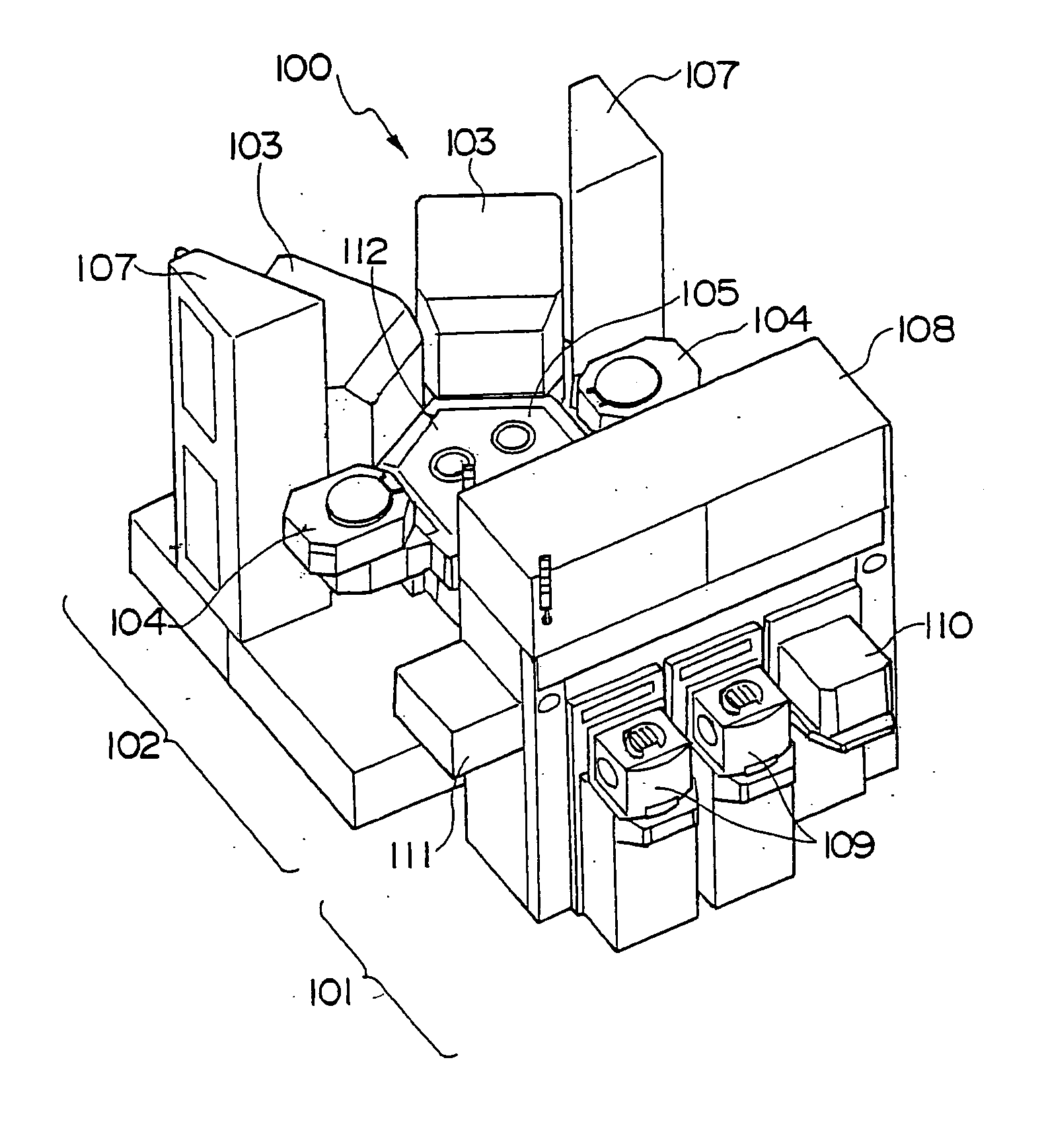
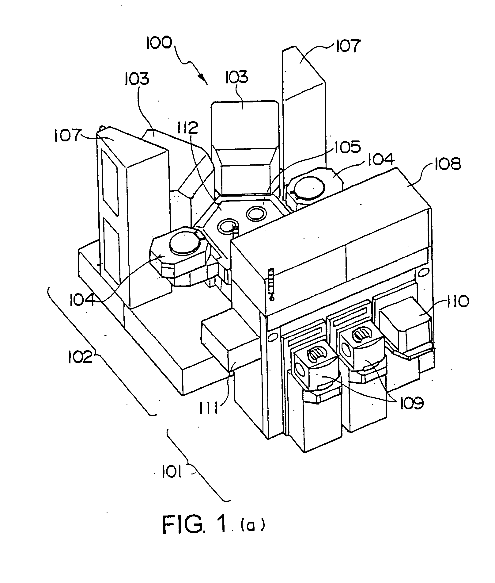
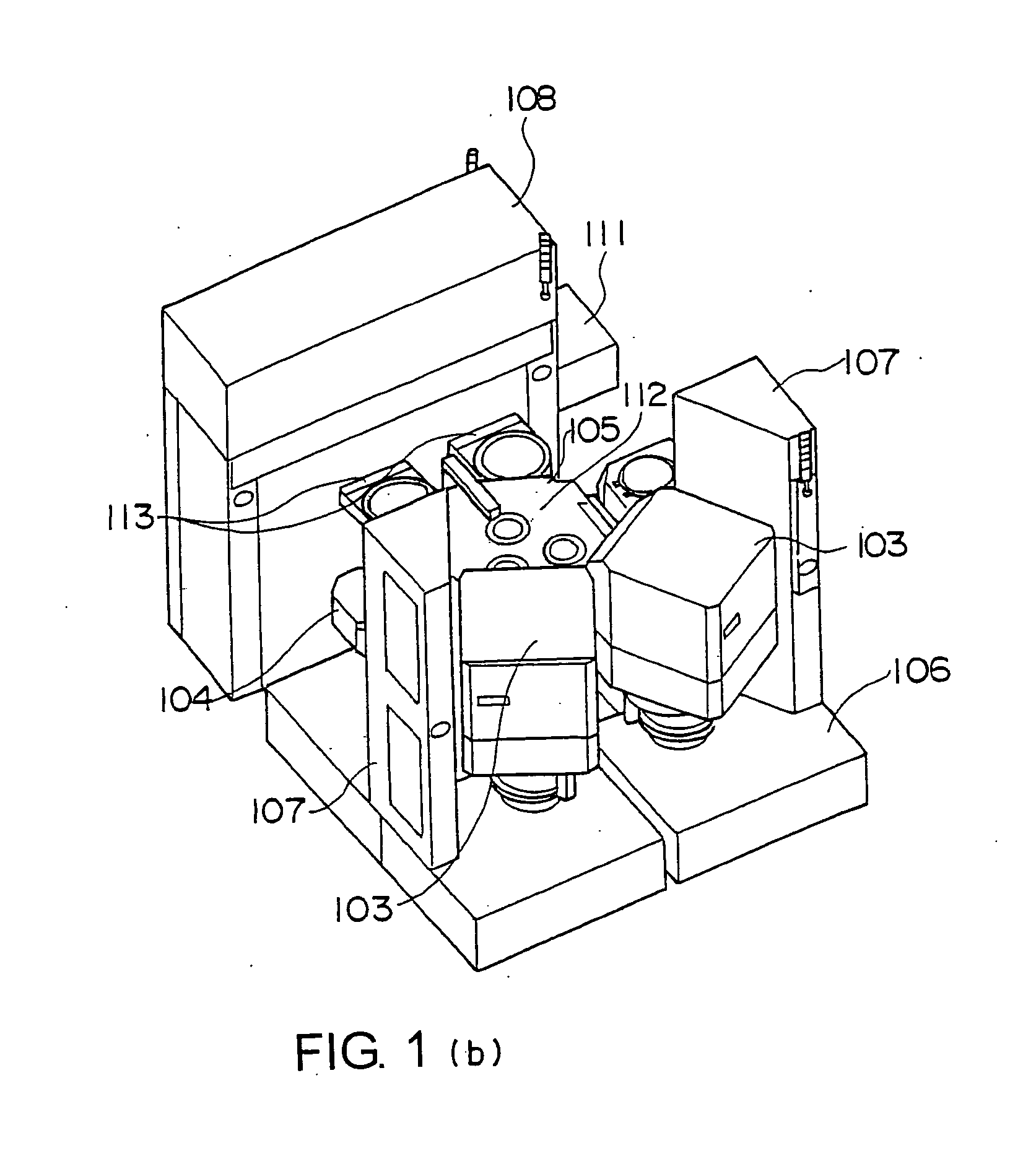
[0032]FIG. 1 is a perspective view showing the overall structure of a vacuum processing apparatus according to a preferred embodiment of the present invention. FIG. 1(a) is a perspective showing the front side, and (b) is a perspective showing the back side thereof. In this drawing, a vacuum processing apparatus 100 according to the present embodiment is largely divided into two, front and back, blocks. The front side of the vacuum processing apparatus body 100 is an atmospheric block 101 in which a wafer supplied to the apparatus is transferred to a chamber decompressed under atmospheric pressure and supplied to a processing chamber. The rear side of the apparatus body 100 is composed of a processing block 102. The processing block 102 comprises processing units 103 and 104 having processing chambers being decompressed for processing wafers, a transf...


PUM


Abstract

A vacuum processing apparatus includes a vacuum processing chamber having a processing table for supporting an object to be processed and carrying out processing using a gas. The vacuum processing chamber has an axisymmetric structure, including a double wall structure, and a gate valve for sealing an opening through which the object enters the processing chamber.

Description

FIELD OF THE INVENTION [0001] The present invention relates to a vacuum processing apparatus for treating an object inside a decompressed apparatus, and especially relates to a vacuum processing apparatus for processing a semiconductor substrate (wafer) using plasma generated within the apparatus. DESCRIPTION OF THE RELATED ART [0002] In the field of vacuum processing apparatuses, especially vacuum processing apparatuses for treating objects within a decompressed chamber, there are increasing demands for enhancing the preciseness of microfabrication of the processes and for improving the efficiency for processing the object wafer. Thus, in recent years, a multiple chamber-type vacuum processing apparatus has been developed in which multiple processing chambers are connected to a single transfer unit, allowing various processes to be performed to the object wafer within a single vacuum processing chamber and there by improving process efficiency. [0003] According to the vacuum proces...

Claims


Application Information

Patent Timeline
IPC IPC(8): C23C16/00H01L21/00
CPCH01L21/67017Y10S414/139Y10S414/135H01L21/6719
Inventor MAKINO, AKITAKATAKAHASHI, YOUJISORAOKA, MINORUKIHARA, HIDEKITAUCHI, SUSUMU
Owner HITACHI HIGH-TECH CORP
Why Eureka
Try Eureka