Setting tool

a technology of a stop member and a clamping rod, which is applied in the direction of nailing tools, manufacturing tools, machines/engines, etc., can solve the problems of the pin becoming jammed in the stop member, and achieve the effect of facilitating the desired deformation of the stop member

Active Publication Date: 2005-03-10
HILTI AG
View PDF4 Cites 13 Cited by
  • Summary
  • Abstract
  • Description
  • Claims
  • Application Information

AI Technical Summary

Benefits of technology

[0017] It is further advantageous when the stop member has a circumferential recess formed in its outer surface and having an arcuate or arc-shaped profile. In the region of the circumferential recess, there is provided, in the stop member wall, a weakness zone that functions as a quasi hinge. Thus, when the setting piston strikes the stop member, the section of the stop member adjacent to the hollow space can be bent-up around this hinge, so that the piston can penetrate into the cylindrical bushing of the stop member by a certain amount.
[0018] It is further advantageous when the ratio of the mass of the setting piston to the mass of the stop member amounts to from 3:1 to 5:1 and is, preferably, 4:1. This ratio of the masses of the setting piston and the stop member also facilitates the desired deformation of the stop member in case of a faulty usage.

Problems solved by technology

With each improper or faulty use, the setting piston with its band penetrates deeper in the cylindrical bushing of the stop member.
When the piston penetrates in the stop member by a predetermined portion of its axial length, the piston becomes jammed in the stop member.

Method used


Image

  • Setting tool
  • Setting tool
  • Setting tool

Examples


Embodiment Construction

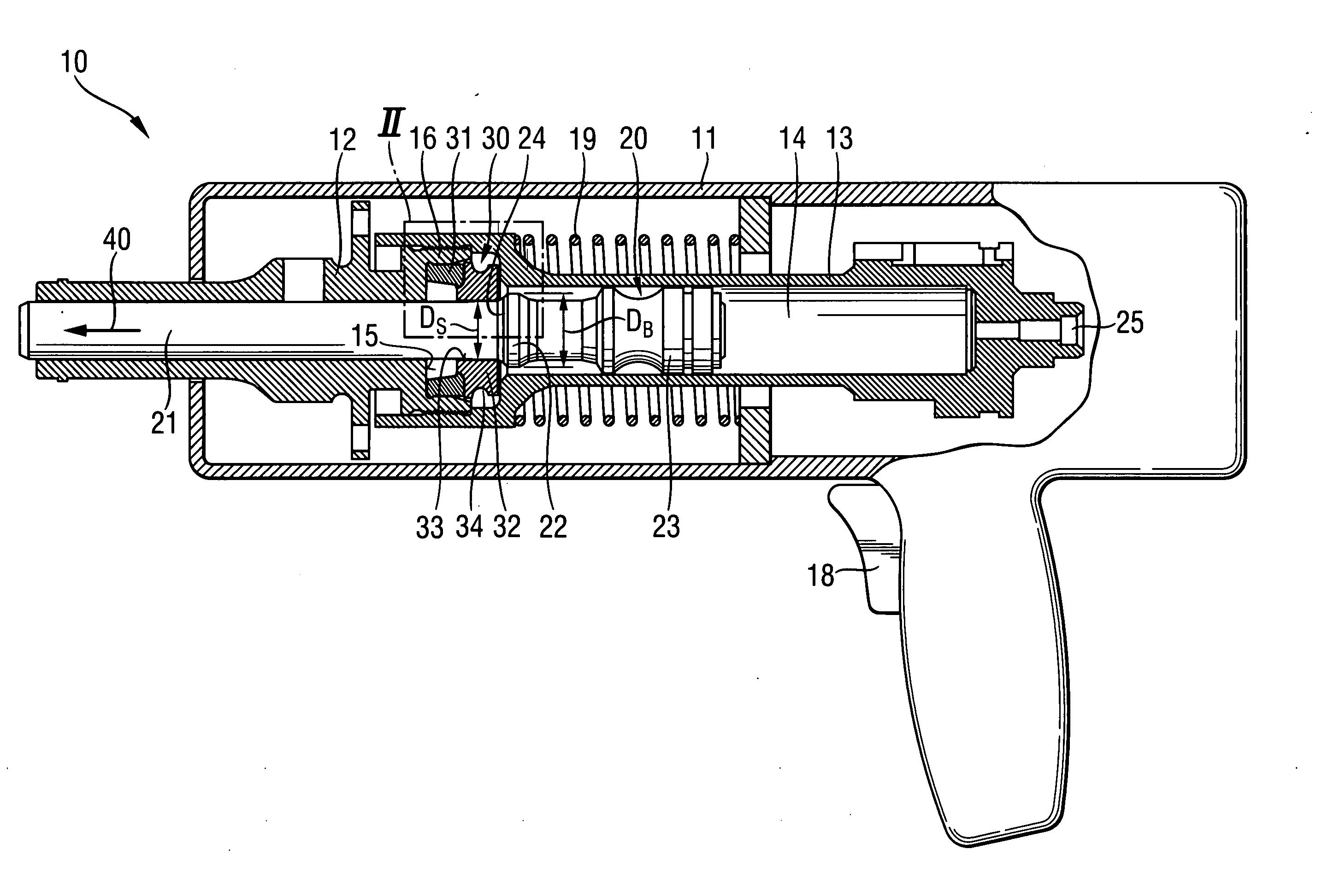
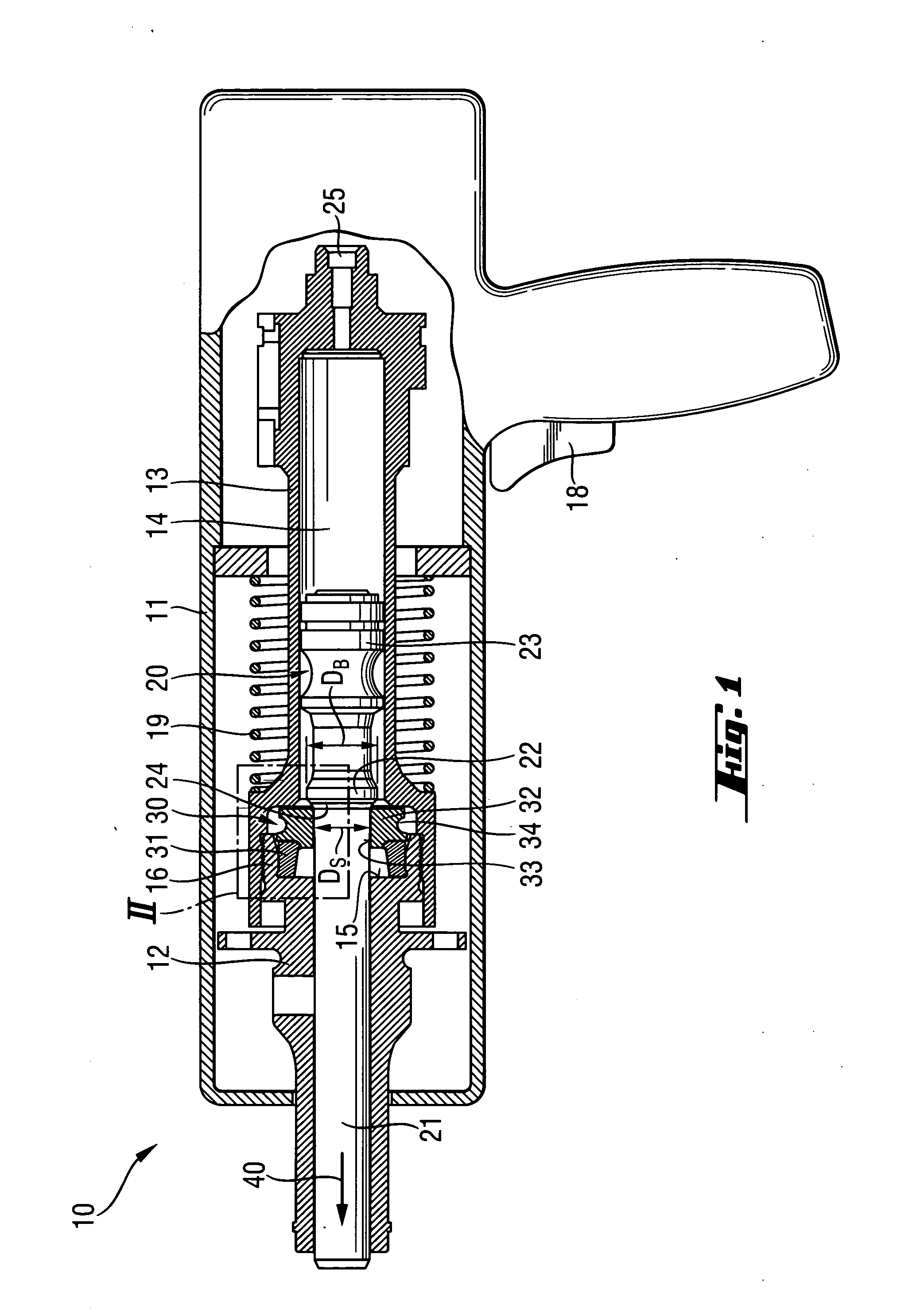
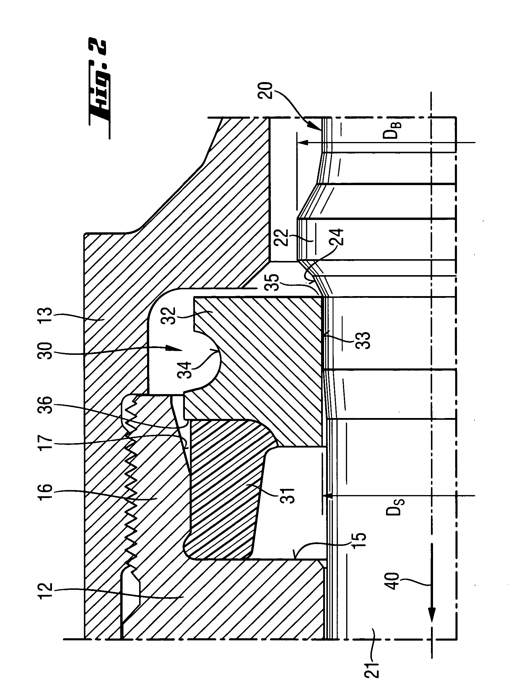
[0026]FIGS. 1-2 show a hand-held setting tool 10 according to the present invention with a piston stop device 30 that has not yet been subjected to any wear. The setting tool 10 has a one-or multi-part housing 11, a piston guide 13 arranged in the housing 11, and a setting piston 20 displaceably arranged in hollow chamber 14 of the piston guide 13. The setting piston 20 is driven by a propellant or by products of its reaction, e.g., by combustion gases, etc. The setting piston 20 has a piston stem 21 and a piston head 23 provided at the rear, in the setting direction 40, end of the stem 21. Spaced from the piston head 23, there is provided, on the stem 21, a band 22. The piston band 22 has a conical surface 24 arranged in the direction of the piston stop device 30. Alternatively to the arrangement shown in the drawings, the band 22 can be arranged in the setting direction region of the piston head 23. The piston guide 13 is displaceably arranged in the curve-shaped housing 11 and is...


PUM


Abstract

A setting tool for driving fastening elements and including a setting piston (20) axially displaceably arranged in the hollow chamber (14) of a piston guide (13), and a piston stop device (30) for the setting piston (20), arranged in setting direction end region of the hollow chamber (14) and having a damping element (31) supported against a stop (15), and a stop member (32) adjoining the damping element (31) in a direction of the hollow chamber (14) and operationally connectable with the piston band (22), and having a cylindrical bushing (33) for the piston stem (21), with the bushing (33) having an inner diameter (DS) that amounts to from 70% to 90% of a size of the maximal outer diameter (DB) of the prison band that has a conical surface engageable with the inner surface of the bushing.

Description

BACKGROUND OF THE INVENTION [0001] 1. Field of the Invention [0002] The present invention relates to a setting tool for driving in fastening elements and including a piston guide having a hollow chamber, a setting piston axially displaceably arranged in the hollow chamber of the piston guide and having a piston head, a piston stem, a piston band, and a piston stop device for the setting piston and arranged in a setting direction end region of the hollow chamber, with the piston stop device having a damping element supported against a stop, and a stop member adjoining the damping element in the direction of the hollow chamber and operationally connectable with the piston band. [0003] 2. Description of the Prior Art [0004] Setting tools of the above-described type are driven with solid, gaseous, or fluid fuels or with compressed air. In combustion-driven setting tools, the setting piston is driven by combustion gases. With these setting tools, fastening elements, such as, e.g., nails ...

Claims


Application Information

Patent Timeline
Patent Type & Authority Applications(United States)
IPC IPC(8): B25C1/14
CPCB25C1/14
Inventor FROMMELT, MARKUSJAKOB, ROBERT
Owner HILTI AG
Why Eureka
Try Eureka