Control system for friction stir welding of metal matrix composites, ferrous alloys, non-ferrous alloys, and superalloys

a technology of friction stir welding and control system, which is applied in the direction of manufacturing tools, soldering devices, metal matrix composites, etc., can solve the problems of insufficient control system for friction stir welding of softer materials, inability to accurately control and inability to meet the needs of friction stir welding, etc., to achieve the effect of improving the wear resistance, improving the control of the tool temperature, and accurate control of the speed of rotation of the tool

Inactive Publication Date: 2005-03-10
SII MEGADIAMOND +3
View PDF20 Cites 43 Cited by
  • Summary
  • Abstract
  • Description
  • Claims
  • Application Information

AI Technical Summary

Benefits of technology

[0012] It is another object to provide a system and method that enables friction stir welding that produces a weld that has consistent and full penetration of the workpieces.
[0013] It is another object to provide a system and method that enables a repeatable friction stir welding that enables assembly-line type of consistency.
[0014] It is another object to provide a system and method that enables friction stir welding of regular welds by accurate control of the speed of rotation of the tool.
[0015] It is another object to provide a system and method that enables friction stir welding by improved control over tool temperature during the friction stir welding pr...

Problems solved by technology

The state of the art in control systems for performing friction stir welding have proven inadequate for friction stir welding of metal matrix composites, ferrous alloys, non-ferrous alloys, and superalloys when using a superabrasive tool.
The fact that the control systems for friction stir welding of softer materials were inadequate surprised the inventors.
These problems include: 1) an uneven weld on the top of the workpieces, 2...

Method used


Image

  • Control system for friction stir welding of metal matrix composites, ferrous alloys, non-ferrous alloys, and superalloys
  • Control system for friction stir welding of metal matrix composites, ferrous alloys, non-ferrous alloys, and superalloys
  • Control system for friction stir welding of metal matrix composites, ferrous alloys, non-ferrous alloys, and superalloys

Examples


Embodiment Construction

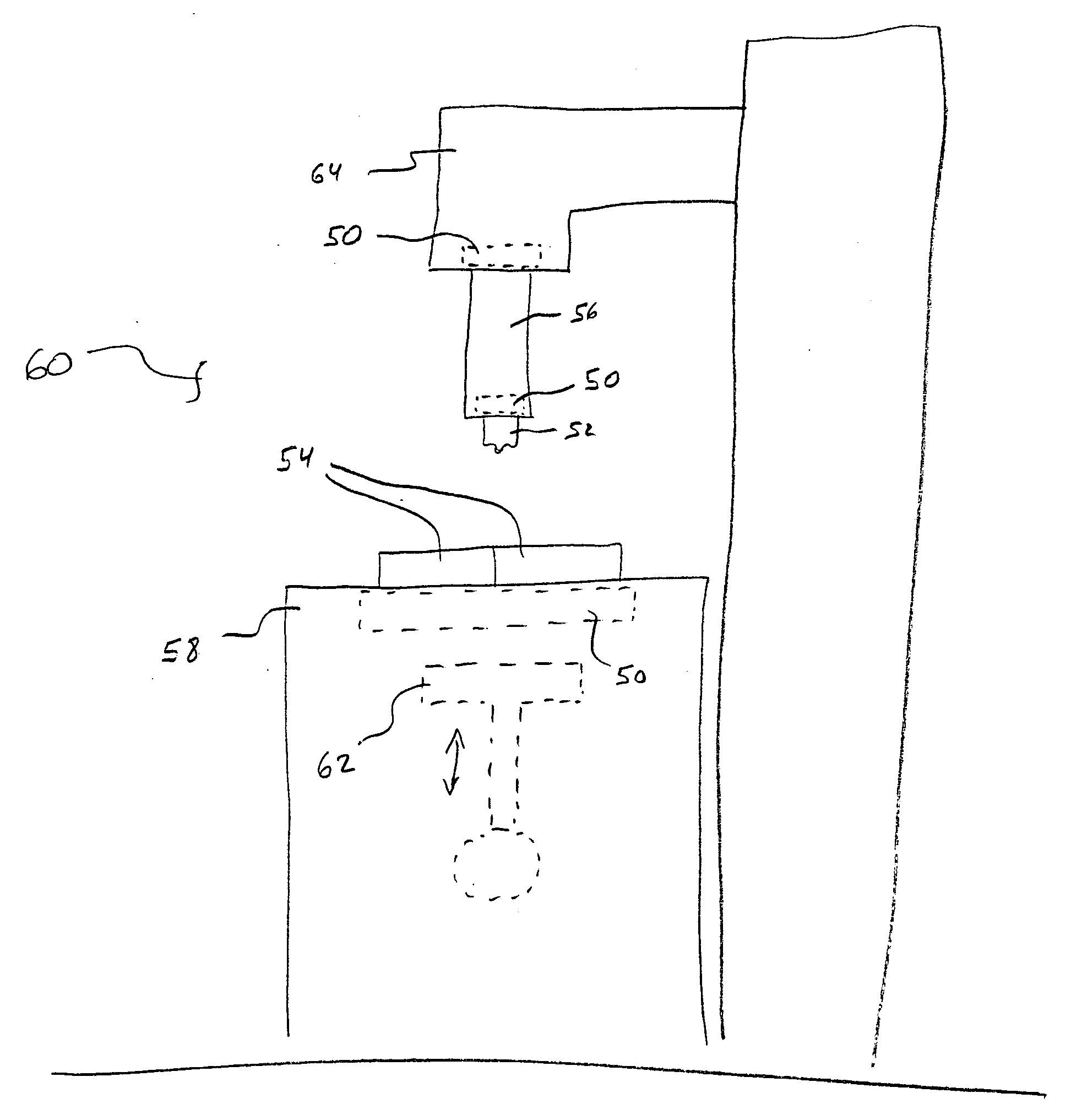
[0028] Reference will now be made to the drawings in which the various elements of the present invention will be given numerical designations and in which the invention will be discussed so as to enable one skilled in the art to make and use the invention. It is to be understood that the following description is only exemplary of the principles of the present invention, and should not be viewed as narrowing the claims which follow.

[0029] The presently preferred embodiment of the invention is a friction stir welding control system and method that makes it possible to friction stir weld metal matrix composites, ferrous alloys, non-ferrous alloys, and superalloys when using a superabrasive tool. Without these improvements to the control system and method, friction stir welding of metal matrix composites, ferrous alloys, non-ferrous alloys, and superalloys when using a superabrasive tool will not be practical or reliable.

[0030] The first aspect of the present invention is referred to ...


PUM

PropertyMeasurementUnit
Forceaaaaaaaaaa
Speedaaaaaaaaaa
Distanceaaaaaaaaaa

Abstract

A control system and method of use that enables friction stir welding of metal matrix composites, ferrous alloys, non-ferrous alloys, and superalloys when using a superabrasive tool, wherein the control system and method enables control of various operational aspects of a friction stir welding mill in order to make it possible to perform friction stir welding that is repeatable, reliable, and results in a superior finished workpiece.

Description

Cross Reference TO RELATED APPLICATIONS [0001] This document claims priority to, and incorporated by reference all of the subject matter included in the provisional patent application docket number 2704.5MII.PR, having Ser. No. 60 / 469,964 and filed on May 13, 2003.BACKGROUND OF THE INVENTION [0002] 1. Field of the Invention [0003] This invention relates generally to friction stir welding wherein heat for creating a weld is generated by plunging a rotating pin of a tool into a workpiece. More specifically, the present invention relates to a control system and a method of use in a friction stir welding process that enables the present invention to weld materials that are not functionally weldable using state of the art friction stir welding processes and tools, said materials including ferrous alloys such as stainless steel, and higher melting point superalloys that contain only small amounts of or no ferrous materials at all. [0004] 2. Description of Related Art [0005] The state of t...

Claims


Application Information

Patent Timeline
IPC IPC(8): B23K20/12
CPCB23K2203/02B23K20/123B23K2103/02
Inventor BABB, JONATHAN ALLYNCONNOLLY, TROYSTEEL, RUSSELL J.PACKER, SCOTT M.NELSON, TRACY W.SORENSEN, CARL D.
Owner SII MEGADIAMOND
Why Eureka
Try Eureka