This orientation is good for riding downhill on the board, but is very uncomfortable when traveling over a flat or uphill
snow contour, when it is necessary to release the back boot and use that boot to propel the board.
Having the front boot nearly perpendicular to the board with the board and back foot moving straight forward is very uncomfortable and potentially dangerous because a fall in this orientation may injure the
ankle or knee joints of the boarder.
Furthermore on a chairlift having the foot nearly perpendicular to the board causes the board to be positioned across the front of the chair which is an awkward orientation for mounting and dismounting and is disturbing or damaging to anyone seated on an adjacent chair.
Mounting and dismounting the chairlift poses a serious danger for potential injury with the foot oriented nearly perpendicular to the board.
The Metzger patent does not have a secure screw-type up and down locking device, a retrofit capability, roller bearings, an elevated lock ring to prevent
icing, a central guide post for ease of alignment during
assembly, a positive engagement safety device to limit the degree of rotatability during
free rotation, an easy grasp elevated L-shaped lock
handle for use with gloves or mittens, or a rotation position indicator for use with the graduated increment sticker, or an L-
handle leash hole and leash, or a top plate overhang to keep
dirt out, or an inner
grease ring to keep
dirt out of the inner shaft, or a series of angle set screws.
The Dawes patent does not have a secure screw-type up and down locking device.
The Dawes patent does not provide an elevated lock ring to prevent
icing, a central guide post for ease of alignment during
assembly, a positive engagement safety device to limit the degree of rotatability during free rotation, or an easy grasp elevated L-shaped lock
handle for use with gloves or mittens, or a rotation position indicator for use with the graduated increment sticker, or an L-handle leash hole and leash, or a top plate overhang to keep dirt out, or an inner
grease ring to keep dirt out of the inner shaft, or a series of angle set screws.
The Donovan patent does not have a secure screw-type up and down locking device and does not have retrofit capability to fit any existing binding, and does not have an elevated lock ring to prevent icing, a central guide post for ease of alignment during
assembly, a positive engagement safety device to limit the degree of rotatability during free rotation, or an easy grasp elevated L-shaped lock handle for use with gloves or mittens, or a rotation position indicator for use with the graduated increment sticker, or an L-handle leash hole and leash, or a top plate overhang to keep dirt out, or an inner grease ring to keep dirt out of the inner shaft, or a series of angle set screws.
The Carpenter patent does not have a secure screw-type up and down locking device and does not have retrofit capability.
Further, Carpenter lacks roller bearings, an elevated lock ring to prevent icing, a central guide post for ease of alignment during assembly, a positive engagement safety device to limit the degree of rotatability during free rotation, an easy grasp elevated L-shaped lock handle for use with gloves or mittens, or a rotation position indicator for use with the graduated increment sticker, or an L-handle leash hole and leash, or a top plate overhang to keep dirt out, or an inner grease ring to keep dirt out of the inner shaft, or a series of angle set screws.
The Vetter patent does not have a secure screw-type up and down locking device, a retrofit capability, roller bearings, an elevated lock ring to prevent icing, a central guide post for ease of alignment during assembly, a positive engagement safety device to limit the degree of rotatability during free rotation, or an easy grasp elevated L-shaped lock handle for use with gloves or mittens, or a rotation position indicator for use with the graduated increment sticker, or a top plate overhang to keep dirt out, or an inner grease ring to keep dirt out of the inner shaft, or a series of angle set screws.
The Hale patent does not have a secure screw-type up and down locking device, a retrofit capability, roller bearings, an elevated lock ring to prevent icing, a central guide post for ease of alignment during assembly, a positive engagement safety device to limit the degree of rotatability during free rotation, or an easy grasp elevated L-shaped lock handle for use with gloves or mittens, or a rotation position indicator for use with the graduated increment sticker, or an L-handle leash hole and leash, or a top plate overhang to keep dirt out, or an inner grease ring to keep dirt out of the inner shaft, or a series of angle set screws.
The Hill patent does not have a secure screw-type up and down locking device, a retrofit capability, roller bearings, an elevated lock ring to prevent icing, a central guide post for ease of alignment during assembly, a positive engagement safety device to limit the degree of rotatability during free rotation, or an easy grasp elevated L-shaped lock handle for use with gloves or mittens or a rotation position indicator for use with the graduated increment sticker, or an L-handle leash hole and leash, or a top plate overhang to keep dirt out, or an inner grease ring to keep dirt out of the inner shaft, or a series of angle set screws.
The Harris patent does not have a secure screw-type up and down locking device, a retrofit capability, roller bearings, an elevated lock ring to prevent icing, a central guide post for ease of alignment during assembly, a positive engagement safety device to limit the degree of rotatability during free rotation, or an easy grasp elevated L-shaped lock handle for use with gloves or mittens or a rotation position indicator for use with the graduated increment sticker, or an L-handle leash hole and leash, or a top plate overhang to keep dirt out, or an inner grease ring to keep dirt out of the inner shaft, or a series of angle set screws.
The Fardie patent does not have a secure screw-type up and down locking device, a retrofit capability, roller bearings, an elevated lock ring to prevent icing, a central guide post for ease of alignment during assembly, a positive engagement safety device to limit the degree of rotatability during free rotation, or an easy grasp elevated L-shaped lock handle for use with gloves or mittens or a rotation position indicator for use with the graduated increment sticker, or an L-handle leash hole and leash, or a top plate overhang to keep dirt out, or an inner grease ring to keep dirt out of the inner shaft, or a series of angle set screws.
The LaVoy patent does not have a secure screw-type up and down locking device, an elevated lock ring to prevent icing, a central guide post for ease of alignment during assembly, a positive engagement safety device to limit the degree of rotatability during free rotation, an easy grasp elevated L-shaped lock handle for use with gloves or mittens, or a rotation position indicator for use with the graduated increment sticker, or an L-handle leash hole and leash, or a top plate overhang to keep dirt out, or an inner grease ring to keep dirt out of the inner shaft, or a series of angle set screws.
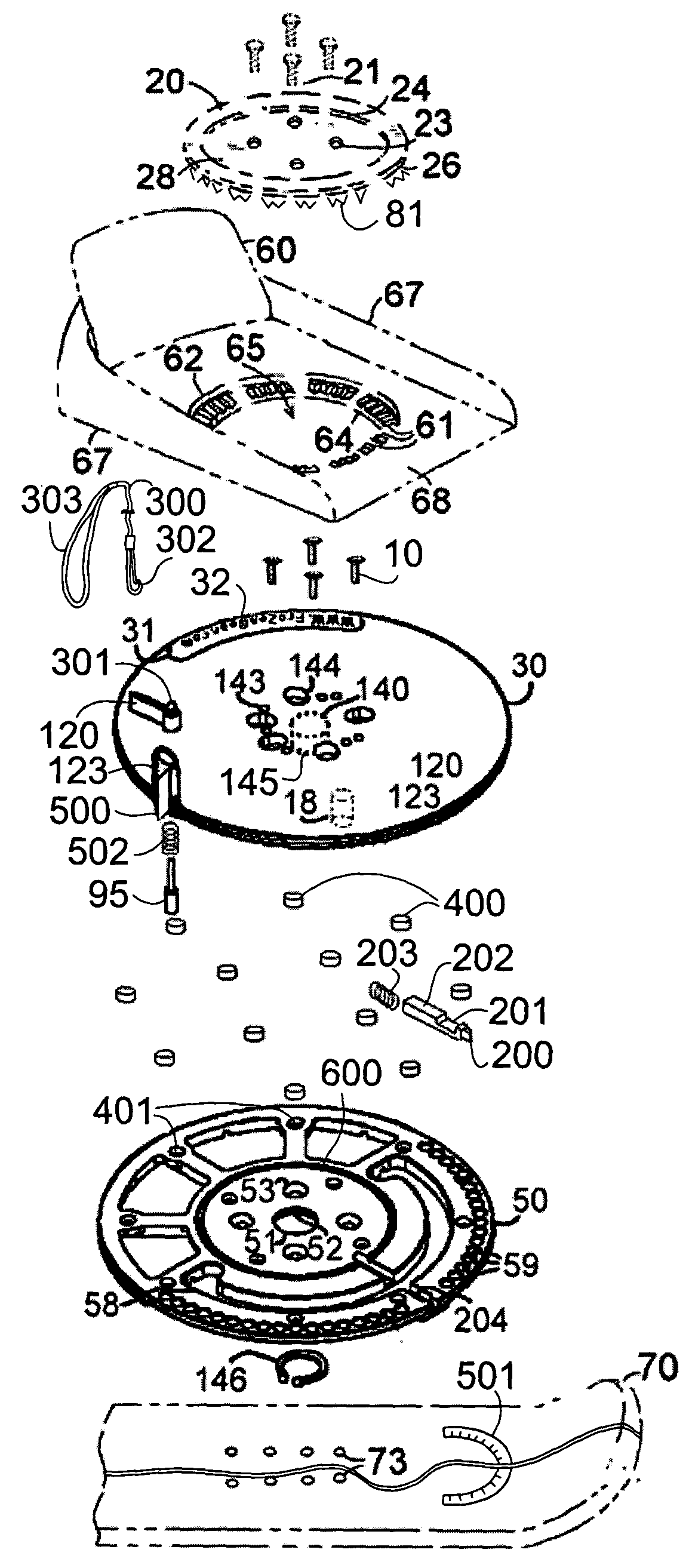
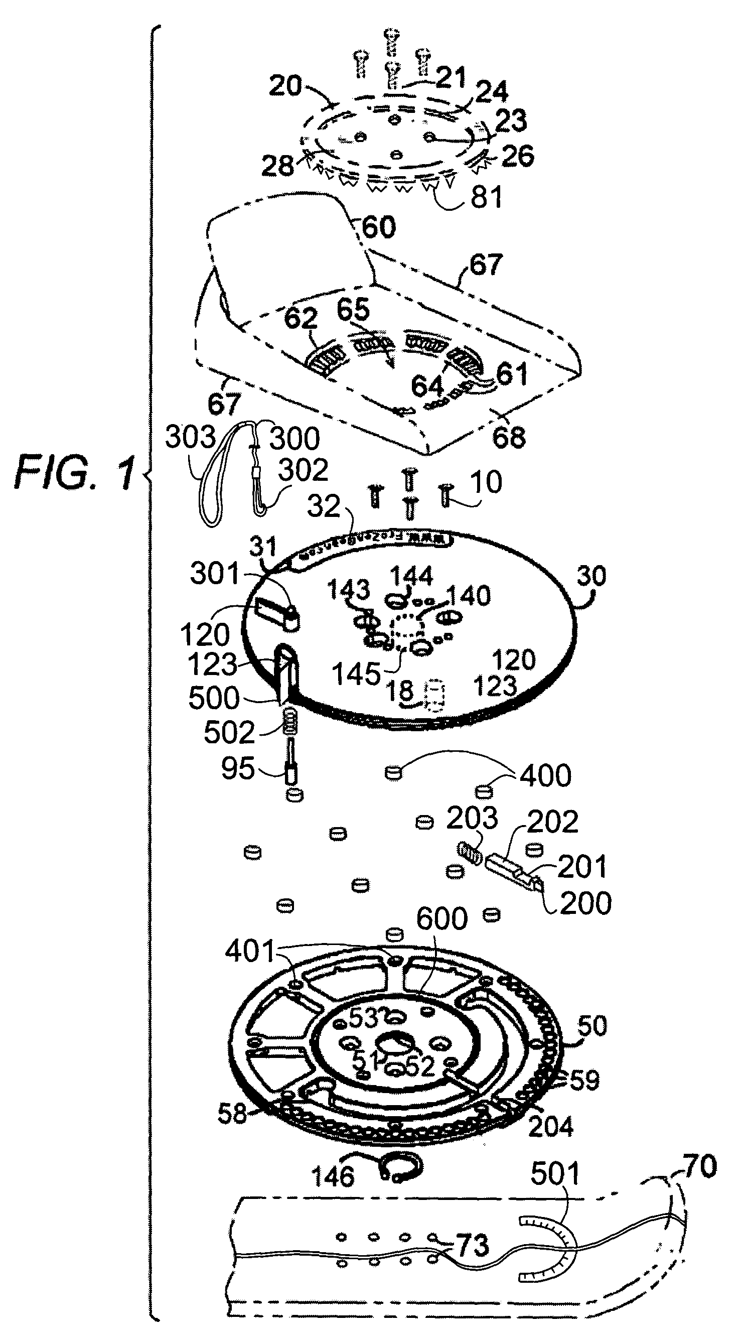
None of the prior art enable a secure locking of the snowboard boot binding in either the hold down position or the freely rotating position.
None of the prior art devices provide an advertising or
identification plate combined with the snowboard binding.
None of the prior art devices provide an adjustable means to allow a rotatable binding apparatus to be used with any of a variety of existing snowboard boots and bindings having two 90 degree rotation
modes.
None of the prior art devices provide a top plate overhang to keep dirt out.
None of the prior art devices provide an inner grease ring to keep dirt out.
None of the prior art devices provide an elevated lock ring to prevent ice from collecting in the holes used for the
locking mechanism.
None of the prior art devices provide a rotation position indicator for use with a graduated sticker.
None of the prior art devices provide an L-handle with a leash hole and a leash to adjust the
angle of rotation from a standing position.
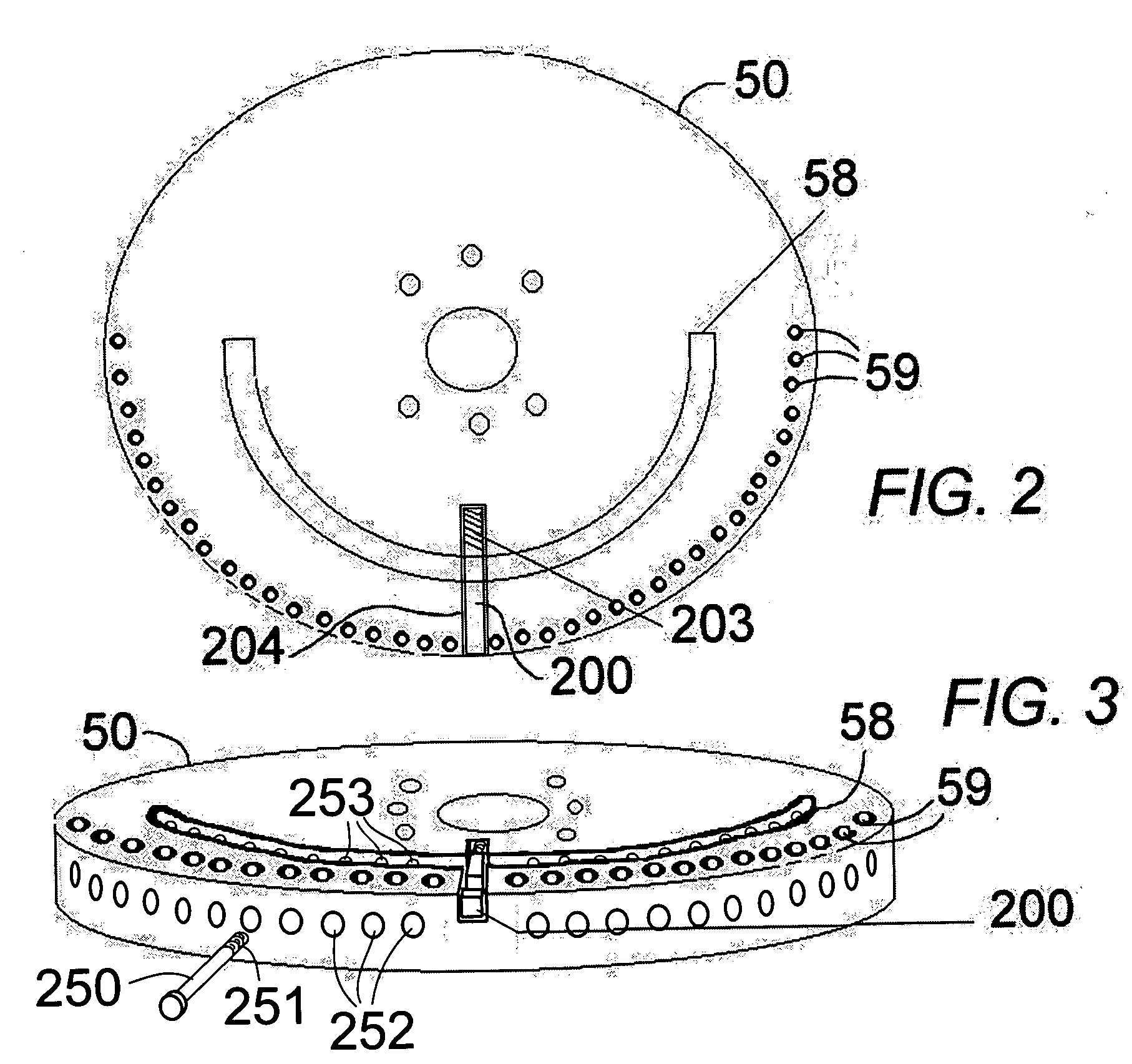
None of the prior art devices provide a series of angle set screws to pre-set the amount of rotation available between the top plate and the bottom plate.

