Reinforced tractor-trailer slider

a tractor-trailer and slider technology, applied in the field of reinforced slider frames, can solve the problems of trailer and/or slider damage, 1, and other slider assemblies, and achieve the effects of reducing weight without compromising structural rigidity, reducing welding beads, and improving the configuration of the slider fram

Inactive Publication Date: 2005-03-10
ARVINMERITOR TECH
View PDF8 Cites 16 Cited by
  • Summary
  • Abstract
  • Description
  • Claims
  • Application Information

AI Technical Summary

Benefits of technology

[0008] In another example embodiment, the continuous wall may be provided by each of a pair of spaced apart horizontal plates. The plates form the central portion, angled portions, and lateral portion. A vertical member is secured between the horizontal plates, and for the example shown, may form an I-beam structure. Braces may be secured between the lateral portion of the upper plate and the longitudinal members, for example. Portions of the structure interconnecting the longitudinal members may include lightening holes in desirable locations to reduce weight without compromising the structural rigidity of the structure.
[0009] Accordingly, the above invention provides an improved slider frame configuration eliminating the need for the reinforcement members while reducing the weld beads required to manufacture the slider frame.

Problems solved by technology

As is known in the art, damage can occur to the slider during adjustment of the slider relative to the trailer.
However, the trailer may be driven without the pins fully engaged with the trailer permitting the slider to collide violently with the trailer causing damage to the trailer and / or slider.
The arrangement in FIG. 1, like other slider assemblies, may become significantly damaged in the event that the slider assembly collides with the trailer.
However, the addition of the inclined members is insufficient such that the reinforcement members are required adjacent to the lateral members.

Method used


Image

  • Reinforced tractor-trailer slider
  • Reinforced tractor-trailer slider
  • Reinforced tractor-trailer slider

Examples


Embodiment Construction

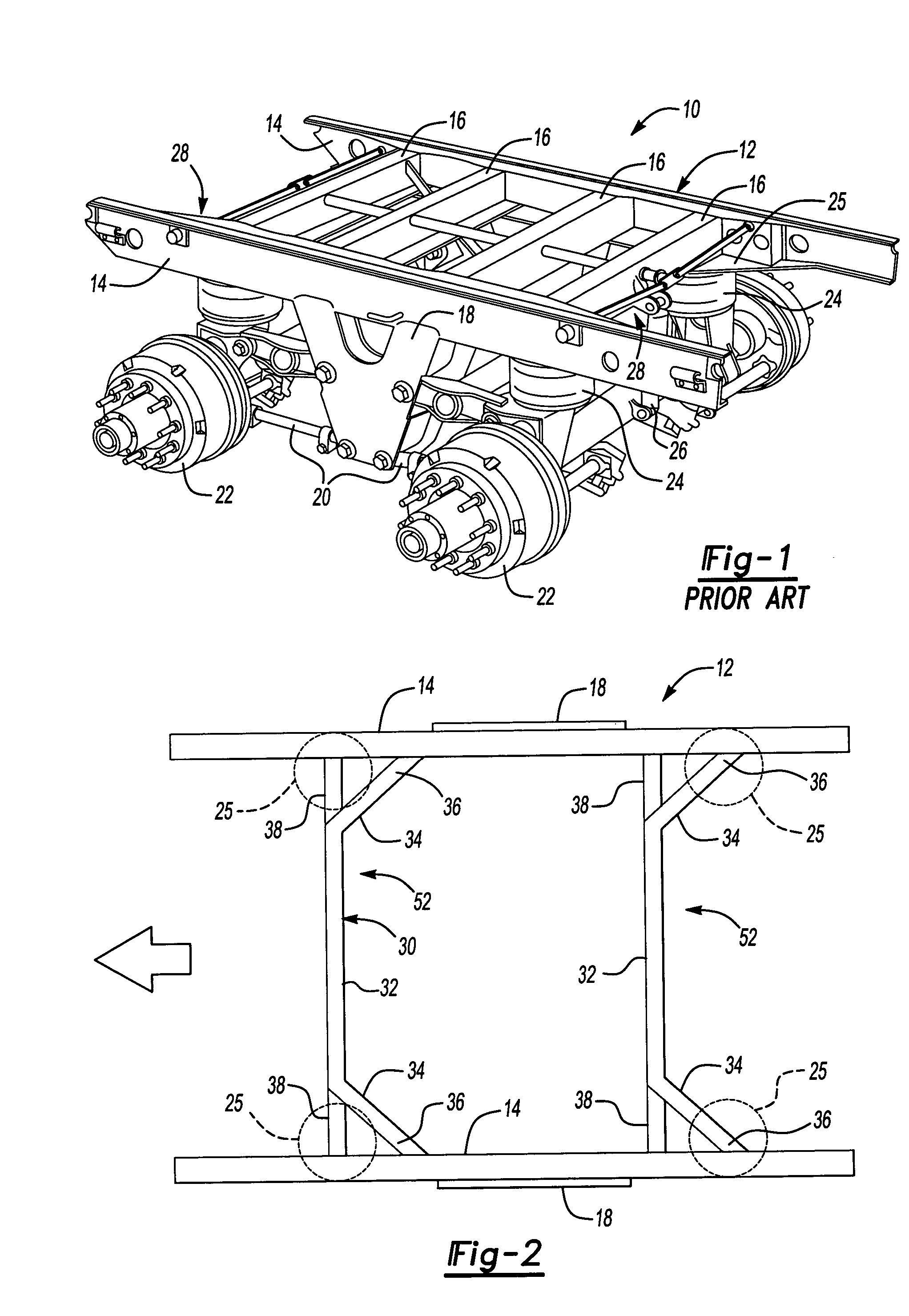
[0020]FIG. 1 depicts an exemplary prior art system having a pair of four bar link suspension assemblies 20 supported by hangers 18. Each suspension assembly 20 has a pair of air springs 24 associated with it and a shock absorber 26 extending between an axle 22 of each suspension assembly 20 and the lateral member 16. One of ordinary skill will appreciate that other suspension assembly configurations may be used with the inventive slider frame, as will be described in more detail below.

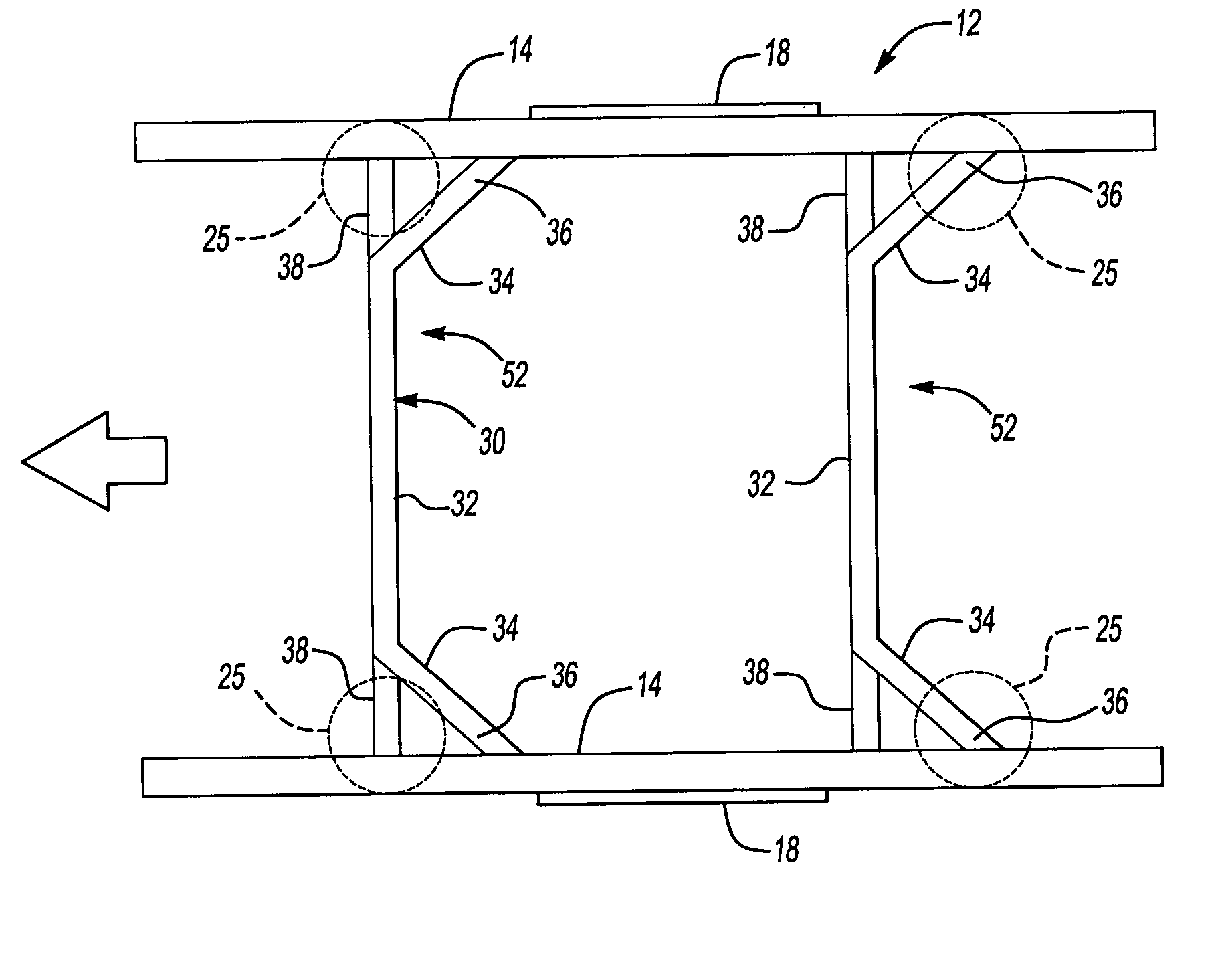
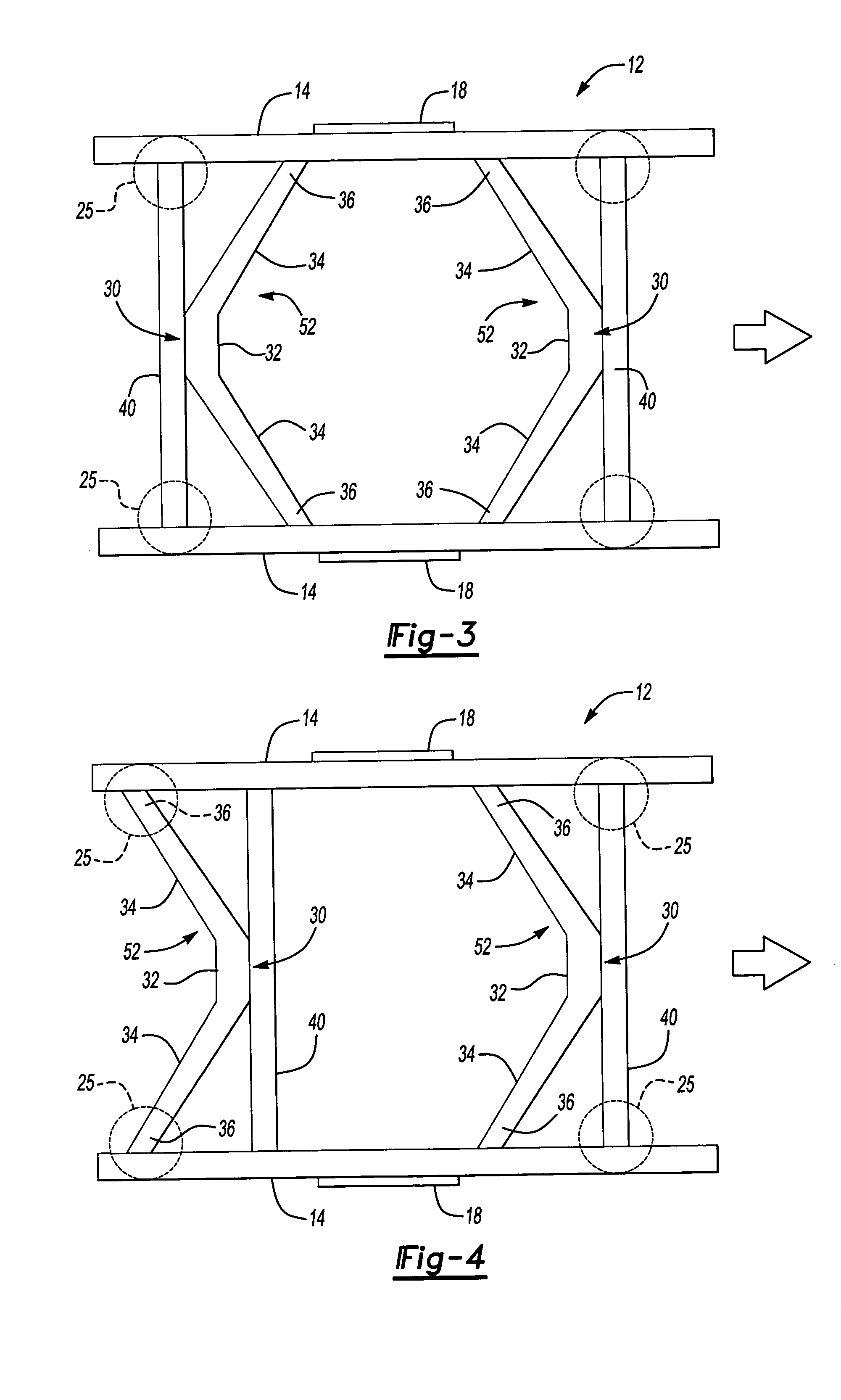
[0021] According to FIG. 2, one example of the inventive bent lateral member 30 is shown extending between the spaced apart longitudinal members 14. Although the front of the slider frame 12 is indicated by the arrow, the slider frame 12 may be oriented differently than shown. The bent lateral member 30 includes a central portion 32 that is generally perpendicular to the longitudinal members 14. A pair of angled portions 34 extend from the central portion 32 at an angle and toward the longitudinal mem...


PUM


Abstract

This present invention provides a suspension slider assembly for a vehicle trailer comprising first and second spaced apart longitudinal members. A structure having a generally continuous, uniform wall is secured between the longitudinal members. The structure also includes a lateral portion extending between the longitudinal members. The wall includes a central portion adjoining opposing first and second angled portions that extend from the central portion at an angle relative to the lateral portion and longitudinal members.

Description

BACKGROUND OF THE INVENTION [0001] This invention relates to a reinforced slider frame for a tractor-trailer slider assembly. [0002] Slider assemblies are well known in the trucking industry and are used to reposition the wheels relative to the trailer to redistribute the load on the axles. As is known in the art, damage can occur to the slider during adjustment of the slider relative to the trailer. Specifically, the slider includes a locking pin assembly that cooperates with a series of holes in the trailer frame to lock the slider frame relative to the trailer in a desired position. To adjust the slider assembly relative to the trailer, the pins are unlocked from the trailer and the tractor is driven to move the trailer forward or rearward relative to the slider assembly. The pins are subsequently locked to the trailer. However, the trailer may be driven without the pins fully engaged with the trailer permitting the slider to collide violently with the trailer causing damage to t...

Claims


Application Information

Patent Timeline
Patent Type & Authority Applications(United States)
IPC IPC(8): B62D21/14B62D33/08B62D53/06
CPCB62D21/14B62D53/068B62D33/08
Inventor SAXON, NANCY L.SAIEG, STEVEN G.HOLT, CRAIGBROMLEY, BRADEN J.
Owner ARVINMERITOR TECH
Why Eureka
Try Eureka