Liquid crystal display apparatus

a liquid crystal display and display device technology, applied in non-linear optics, instruments, optics, etc., can solve the problem of not being able to accommodate the contact hole of the column spacer, and achieve the effect of improving the effective open area ratio of display and improving display quality

Active Publication Date: 2005-03-10
UNIFIED INNOVATIVE TECH
View PDF8 Cites 38 Cited by
  • Summary
  • Abstract
  • Description
  • Claims
  • Application Information

AI Technical Summary

Benefits of technology

[0031] This invention has been achieved to solve the problems described above, and an object thereof is to provide a liquid crystal display apparatus in which even in the case where a pair of substrates attached to each other for h

Problems solved by technology

Even in the case where the substrates attached to each other are displaced from e

Method used


Image

  • Liquid crystal display apparatus
  • Liquid crystal display apparatus
  • Liquid crystal display apparatus

Examples


first example

(FIRST EXAMPLE)

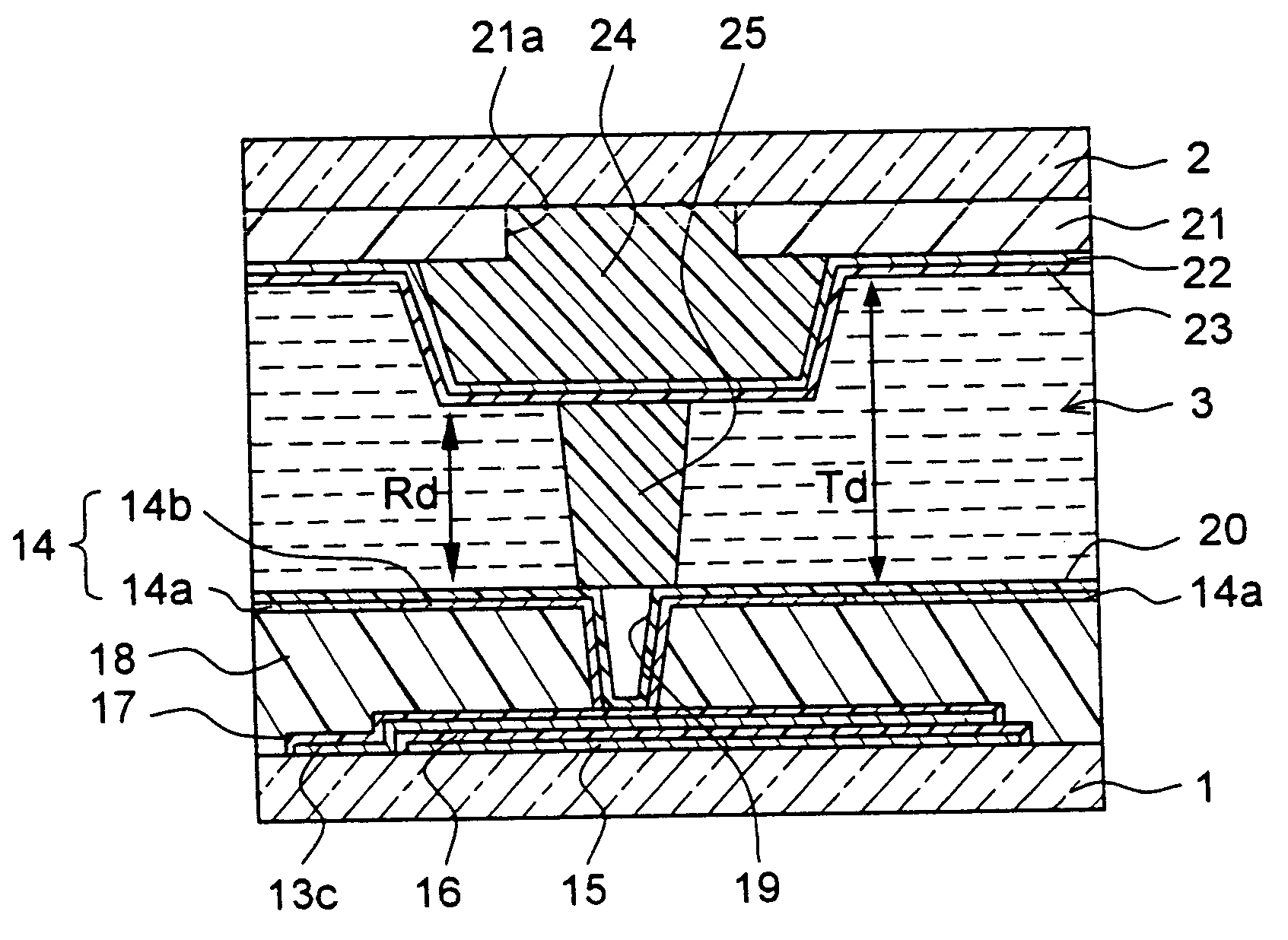
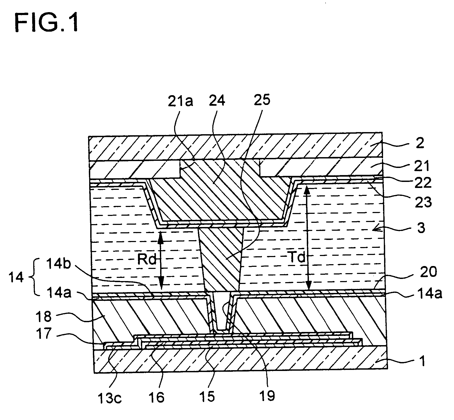
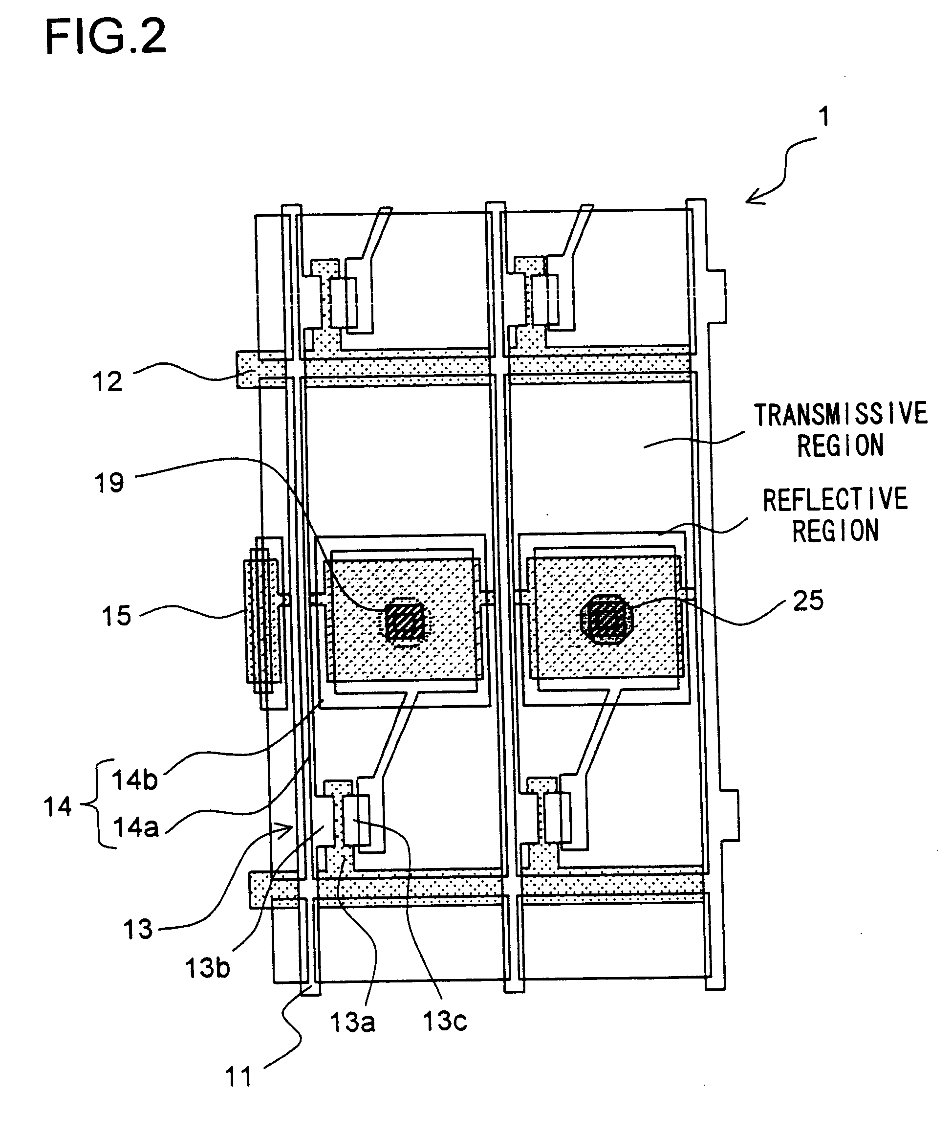
[0142]FIG. 11 is a plan view showing the first substrate 1 of the liquid crystal display apparatus according to this example. In this example, the columnar spacer 25 has a rectangular cross section in the size of 30 μm by 7 μm (sectional area of 210 μm2) and is arranged in superposition with a part of the contact hole 19.

[0143] In this example, each columnar spacer 25 is formed on the side of the first substrate 1 formed with the TFT 13. Even in the case where the first substrate 1 and the second substrate 2 attached to each other are displaced from each other, therefore, the position of the columnar spacer 25 relative to the contact hole 19 remains unchanged. In this example, therefore, unlike in the second and third examples described later, the displacement (5 μm) between the substrates attached to each other is not taken into consideration.

[0144] In this example, the sectional area of the columnar spacer 25 is 210 μm2, which is larger than the grounding area 185...

second example

(SECOND EXAMPLE)

[0146] According to this example, in the configuration shown in FIG. 9 (second embodiment) with the columnar spacer 25 arranged on the side of the second substrate 2, the columnar spacer 25 has a cross section in the shape of an octagon circumscribed about the circle having a radius of 10

[0147]μm. For the reason of fabricating a mask to produce the columnar spacer 25, the cross section of the columnar spacer 25 according to this example is not a regular octagon. More specifically, in the cross section of the columnar spacer 25, each the four alternate sides of the eight sides making up the octagon has the length of, say, 8 μm, while the remaining four sides (four sides located between each pair of 8-μm sides) each have the length of, say, 8.4 μm. According to this example, therefore, the sectional area of the columnar spacer 25 is given as (8×10×4) / 2+(8.4×10×4) / 2=328 μm2.

[0148] The columnar spacer 25 having an octagonal cross section as in this example is designed,...

third example

(THIRD EXAMPLE)

[0150]FIG. 12 is a plan view showing the first substrate 1 of the liquid crystal display apparatus according to this example. In this example, the columnar spacer 25 has a trapezoidal cross section. This trapezoid has, for example, the upper side 4 μm long, the lower side 12 μm long, the height of 31 μm and the area of 248 μm2. The columnar spacer 25 is formed on the side of the second substrate 2 in superposition with a part of the contact holes 19.

[0151] Various calculations show that in the case where the columnar spacer 25 has a trapezoidal cross section of the size described above and the substrates attached to each other are displaced horizontally by 5 μm, for example, the grounding area of 185 μm2 can be maintained in the absence of vertical displacement. It is also known from various calculations that in the case where the substrates are displaced vertically by 5 μm and horizontally by not more than 4.3 μm, for example, the grounding area of 185 μm2 can be ma...


PUM


Abstract

A columnar spacer is interposed between a first substrate and a second substrate for holding a liquid crystal layer between them. The columnar spacer is formed in such a manner as to have an area superposed, in each pixel, with the contact hole formed in the first substrate and an area not superposed with said contact hole. Even in the case where the first and second substrates attached to each other are displaced from each other, the columnar spacer never falls in the contact hole and a desired cell gap can be positively secured. Also, since the columnar spacer is not located in the contact hole, no margin for substrate attachment is required to form the contact hole in the first substrate, thereby improving the open area ratio effective for display for improved display quality.

Description

[0001] This Nonprovisional application claims priority under 35 U.S.C. § 119(a) on Patent Application No. 2003-315550 filed in Japan on Sep. 8, 2003 and Patent Application No. 2004-226279 filed in Japan on Aug. 3, 2004, the entire contents of which are hereby incorporated by reference. BACKGROUND OF THE INVENTION [0002] 1. Field of the Invention [0003] The present invention relates to a liquid crystal display apparatus wherein a pair of substrates holding a liquid crystal layer therebetween are attached to each other through a columnar spacer. [0004] 2. Description of the Prior Art [0005] In recent years, a liquid crystal display apparatus, taking advantage of the features that it is both thin and low in power consumption, has been widely used for OA equipment such as a word processor and a personal computer, the portable information equipment such as an electronic dictionary or a single-unit video tape recorder having a liquid crystal monitor. [0006] The liquid crystal display appa...

Claims


Application Information

Patent Timeline
IPC IPC(8): G02F1/1337G02F1/1339G02F1/1343G02F1/1368
CPCG02F1/13394G02F1/133371G02F2201/50G02F1/136227G02F1/133555G02F1/1339
Inventor MORI, JUNICHIUEMURA, SHIGERUKIKUCHI, KATSUHIROYOSHIDA, MASAHIRO
Owner UNIFIED INNOVATIVE TECH
Why Eureka
Try Eureka