Method and system for measuring stray light

a technology of exposure apparatus and stray light, which is applied in the direction of optical radiation measurement, photomechanical apparatus, instruments, etc., can solve the problems of significant influence on the accuracy and reliability of measured data, time-consuming process of obtaining measurement data, and significant influence on the performance of semiconductor devices. achieve the effect of fast and effective stray light measuremen

Active Publication Date: 2005-03-10
SAMSUNG ELECTRONICS CO LTD
View PDF5 Cites 22 Cited by
  • Summary
  • Abstract
  • Description
  • Claims
  • Application Information

AI Technical Summary

Benefits of technology

[0009] It is a feature of an embodiment of the present invention to measure stray light dispersed within a few microns range in an exposure apparatus. It is another feature of an embodiment of the present invention to measure stray light dispersed within tens of microns. It is yet another feature of an embodiment of the present invention to provide fa...

Problems solved by technology

When using such an exposure apparatus, e.g., a photo scanner, flares caused by stray light when transcribing a reticle pattern on a wafer significantly affect performance of semiconduct...

Method used


Image

  • Method and system for measuring stray light
  • Method and system for measuring stray light
  • Method and system for measuring stray light

Examples


first embodiment

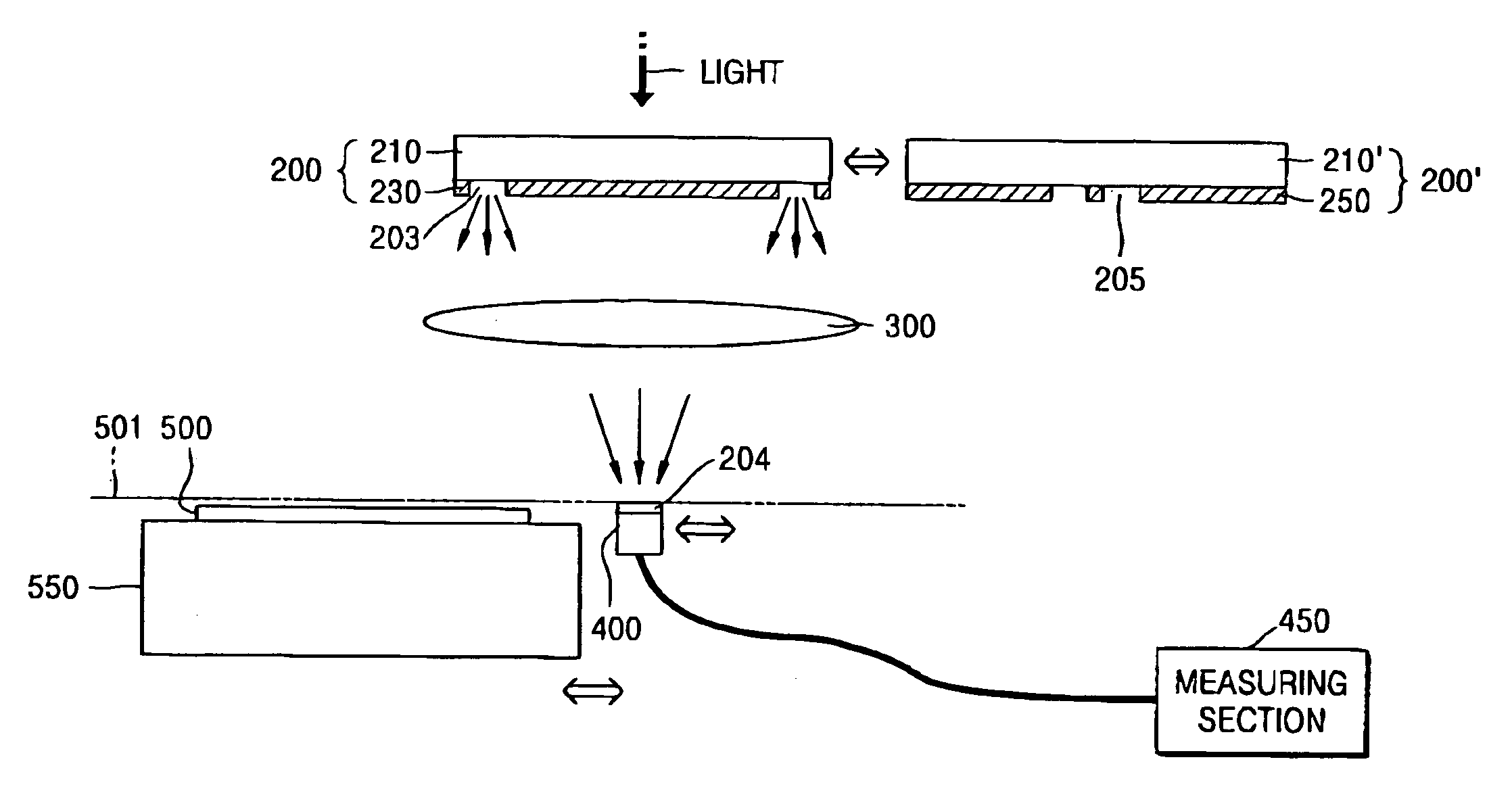
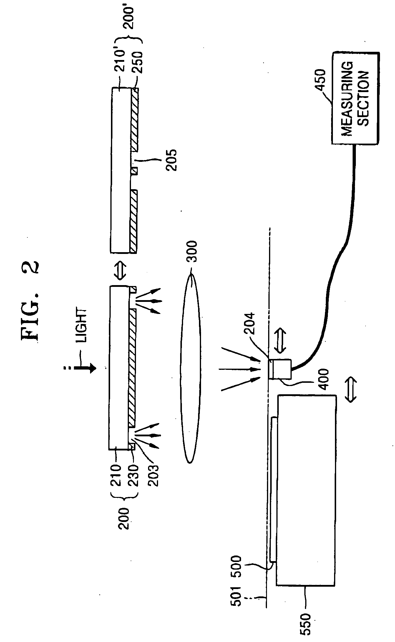
[0037] Therefore, in the present invention, the size (or width) of the photo sensing region is relatively large, i.e., larger than needed to measure stray light, so that it can be used not only for measuring stray light, but also for focusing and aligning a wafer. That is, the width of a sensing region 204 of the image sensor 400 may be a few tens of microns, e.g., a length of a side of the square is a few tens microns with respect to the size of the reticle.

[0038] If the size of the photo sensing region 204 is a few tens of microns, the intensity data of the sensed stray light within a range of a few microns, more specifically, about 1˜20 μm, and, more practically, up to about 10 μm, cannot be used for evaluating an effect of stray light. In order to solve this problem, a measuring pattern system as depicted in FIGS. 3A and 3B is introduced in accordance with the first embodiment of the present invention.

[0039] Referring to FIGS. 2, 3A, and 3B, the measuring pattern system include...

second embodiment

[0063] Referring to FIGS. 5 and 6, a stray light measuring pattern system having an opaque pattern 270 is formed on a transparent substrate 210 of a reticle 200, in step 510. In the second embodiment, the measuring pattern system includes the opaque pattern 270 in addition to the measuring pattern 230 and the reference pattern 250 as described with reference to FIGS. 3A and 3B. The opaque pattern 270 can be formed on the same transparent substrate 210 of the reticle 200 as the measuring pattern 230 and the reference pattern 250, or can be formed on a separate transparent substrate.

[0064] The opaque pattern 270 is surrounded by a third open or transparent region 207. The third open region 207 is a light transmitting region, while the opaque pattern 270 is a light shielding or blocking region. The opaque pattern 270 may be sufficiently large to cover the photo sensing region 204 when the opaque pattern 270 is positioned over the sensor 400.

[0065] Using the opaque pattern 270, stray l...


PUM


Abstract

A method and system for measuring stray light for use in an exposure apparatus uses an image sensor to be disposed at a wafer level in the exposure apparatus. The stray light is measured by preparing a reference pattern and a measuring pattern on a reticle. The reference pattern includes a light shielding region having first open regions for transmitting light to a center of an active region of the image sensor. The measuring pattern includes a light shielding region having second open regions for transmitting light to a periphery of the active region. A first intensity of light reaching the active region after being filtered by the reference pattern and a second intensity of light reaching the image sensor after being filtered by the measuring pattern are measured. The intensity of the stray light is evaluated by a difference between the first and second light intensities.

Description

BACKGROUND OF THE INVENTION [0001] 1. Field of the Invention [0002] The present invention relates to an exposure apparatus used for manufacturing semiconductor devices. More particularly, the present invention relates to a method of and a system for measuring stray light in an exposure apparatus. [0003] 2. Description of the Related Art [0004] A variety of exposure apparatuses for transcribing a pattern on a wafer are used for manufacturing semiconductor devices. When using such an exposure apparatus, e.g., a photo scanner, flares caused by stray light when transcribing a reticle pattern on a wafer significantly affect performance of semiconductor devices made thereby. Therefore, it is important to minimize stray light in an exposure apparatus. [0005] A widely used method for measuring stray light is the Kirk method. In the Kirk method, stray light is evaluated by measuring an exposure dose at which a predetermined size of an opaque pattern disappears due to the stray light. [0006] ...

Claims


Application Information

Patent Timeline
IPC IPC(8): G03F7/20H01L21/027G03F9/00
CPCG03F7/7085G03F9/7088G03F7/70941H01L21/027
Inventor KIM, HO-CHUL
Owner SAMSUNG ELECTRONICS CO LTD
Why Eureka
Try Eureka