Method and apparatus to generate tracking error signal, optical storage drive using the same, and lead-in control method for the optical storage drive

a technology of optical storage drive and tracking error, which is applied in the direction of digital signal error detection/correction, instruments, recording signal processing, etc., can solve the problems of lead-in failure or preventing data from being reproduced from the cd, and the 3 beam method is no longer used,

Inactive Publication Date: 2005-03-10
SAMSUNG ELECTRONICS CO LTD
View PDF0 Cites 6 Cited by
  • Summary
  • Abstract
  • Description
  • Claims
  • Application Information

AI Technical Summary

Benefits of technology

Additional aspects and / or advantages of the invention will be set forth in part in the description which follows and, in part, will be obvious from the description, or may be learned by practice of the invention.

Problems solved by technology

However, the 3-beam method is not used any longer because the 3-beam method is not compatible with a recordable disc such as a CD-R.
This method is useable for DVDs but cannot be used for recordable discs, such as CDs-R and DVDs-RAM, which have blank regions in which data is not recorded.
Since the DPP method is based on the PP method, a magnitude of a tracking error signal generated using the DPP method is too small to satisfactorily perform a tracking control when reproducing data from a CD with a pit depth of around λ / 4 or a narrow track pitch, thereby causing a lead-in failure or preventing data from being reproduced from the CD.

Method used


Image

  • Method and apparatus to generate tracking error signal, optical storage drive using the same, and lead-in control method for the optical storage drive
  • Method and apparatus to generate tracking error signal, optical storage drive using the same, and lead-in control method for the optical storage drive
  • Method and apparatus to generate tracking error signal, optical storage drive using the same, and lead-in control method for the optical storage drive

Examples


first embodiment

FIG. 10 is a flowchart illustrating a method of generating a tracking error signal according to the present invention. Referring to FIG. 10, whether a media inserted into an optical storage drive is a CD or not is checked, in operation 1002. If in operation 1002 the media is determined to be a CD, a laser diode suitable for the CD is driven to generate an optical signal in operation 1004.

In operation 1006, one or more laser beams, which are emitted from the laser diode for the CD and reflected from the CD, are received by a four-divided photo detector. In this case, the four-divided photo detector corresponds to the main photo detector 32 of FIG. 5, which receives light corresponding to the main spot MS, as shown in FIG. 5.

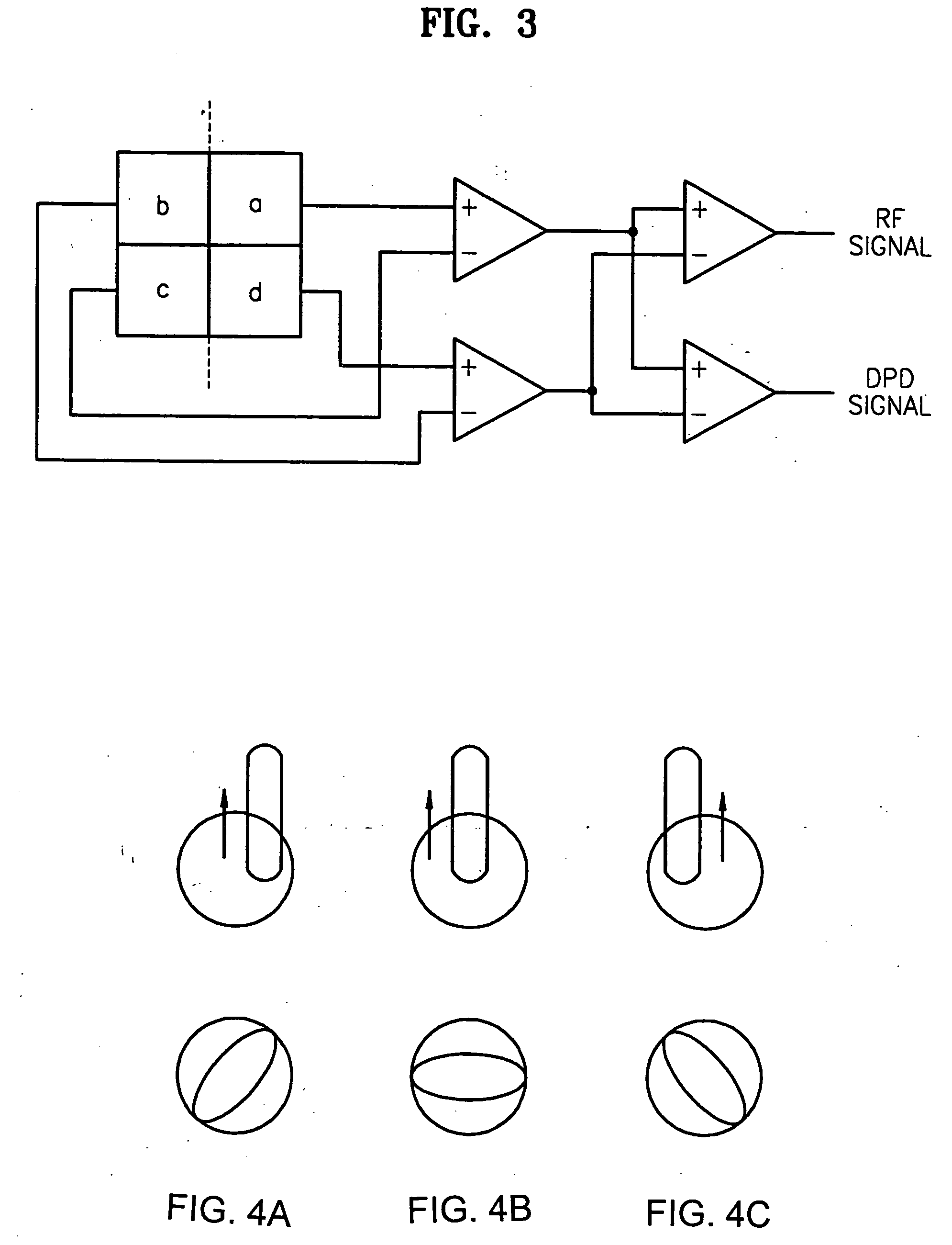
In operation 1008, a tracking error signal is generated by calculating a diagonal difference signal of optical signals received by the four-divided main photo detector 32. That is, the tracking error signal is obtained as DPD=(A+C)−(B+D).

An apparatus to gener...

second embodiment

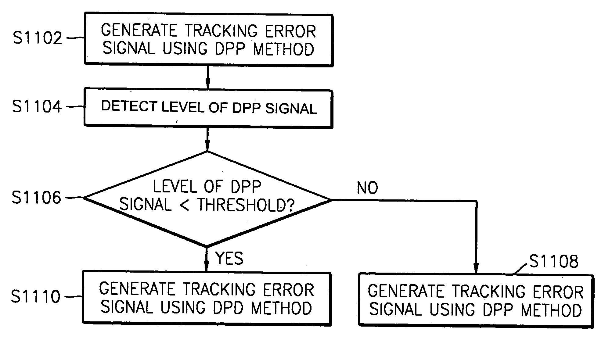
FIG. 11 is a flowchart illustrating a method of generating a tracking error signal, according to the present invention. Referring to FIG. 11, if a media inserted into in an optical storage drive is a CD, a tracking error signal is generated using the DPP method in operation 1102. In operation 1104, a level of a DPP signal is detected. In operation 1106, the level of the DPP signal is compared with a predetermined threshold. In operation 1108, the tracking error signal is generated using the DPP method when the level of the DPP signal is the same as or larger than the predetermined threshold. However, the tracking error signal is generated using the DPD method when the level of the DPP signal is less than the predetermined threshold, in operation 1110.

third embodiment

FIG. 12 is a block diagram illustrating a structure of an apparatus 1200 that generates a tracking error signal according to the present invention. The apparatus 1200 generates a tracking error signal for a CD with an optical detection signal generated by a photo detector that generates an electrical signal corresponding to an intensity of a laser beam reflected from a CD surface.

The apparatus 1200 includes a first tracking error signal generator 1202 that receives an optical detection signal input from a first input terminal 1210 and generates a tracking error signal with the optical detection signal using the DPD method; a second tracking error signal generator 1204 that receives an optical detection signal input from the first input terminal 1210 and generates a tracking error signal with the optical detection signal using the DPP method; a comparator 1206 that compares an output of the second tracking error signal generator 1204 with a predetermined threshold Th; and a selector...


PUM

PropertyMeasurementUnit
differential phase detection methodaaaaaaaaaa
thresholdaaaaaaaaaa
wavelengthsaaaaaaaaaa

Abstract

A method and apparatus to stably generate a tracking error signal even for a compact disc (CD) with a pit depth of about λ / 4 or a narrow track pitch in an optical storage drive, an optical storage drive using the same, and a lead-in control method of the optical storage drive. The method includes detecting reflected laser beams using a photo detector; and generating a first tracking error signal based on optical signals received by the photo detector, using a differential phase detection (DPD) method and outputting the first tracking error signal as the tracking error signal.

Description

CROSS REFERENCE TO RELATED APPLICATIONS This application claims the priority of Korean Patent Application Nos. 2002-75298 filed Nov. 29, 2002 and 2003-23060 filed Apr. 11, 2003, respectively, in the Korean Intellectual Property Office, the disclosure of which is incorporated herein by reference. BACKGROUND OF THE INVENTION 1. Field of the Invention The present invention relates to a method and apparatus to generate a tracking error signal in an optical storage drive, and more particularly, to a method and apparatus to stably generate a tracking error signal even with a compact disc (CD) with a pit depth of around λ / 4 or a narrow track pitch, an optical storage drive using the method and apparatus, and a lead-in control method of the optical storage drive. 2. Description of the Related Art In general, optical discs on which data is written and from which data is read by lasers include CDs and digital versatile discs (DVDs), on which rewriting is not possible, compact discs recor...

Claims


Application Information

Patent Timeline
Patent Type & Authority Applications(United States)
IPC IPC(8): G11B7/09G11B7/00G11B7/085
CPCG11B7/0903G11B2007/0006G11B7/0945G11B7/0906
Inventor PARK, CHANG-SOOLEE, JONG-GYOUKO, SEONG-KYUN
Owner SAMSUNG ELECTRONICS CO LTD
Why Eureka
Try Eureka