Thermal analyzer provided with cooling mechanism

a technology of cooling mechanism and thermometer, which is applied in the direction of material thermal analysis, calorimeter, instruments, etc., can solve the problems of cumbersome exchange of cooling head, inability to perform cooling of 100° c. or below, and increase the gas consumption, so as to improve the efficiency of measurement and reduce the load of gas cooling device, the effect of reducing the cooling tim

Active Publication Date: 2005-03-10
HITACHI HIGH TECH SCI CORP +1
View PDF12 Cites 10 Cited by
  • Summary
  • Abstract
  • Description
  • Claims
  • Application Information

AI Technical Summary

Benefits of technology

[0012] Further, due to the use of the electric cooling device and the gas cooling device in combination, a load of the gas cooling device can be reduced and hence, a consumption amount of gas can be suppressed whereby a load attributed to the replenishment of liquefied nitrogen can be reduced.
[0013] Further, due to the use of the electric cooling device and the gas cooling device in combination, the heat sink can be rapidly cooled whereby the cooling time can be shortened thus realizing the enhancement of the efficiency of the measurement.

Problems solved by technology

Accordingly, when the gas cooling device is used, although the cooling can be performed up to −150° C., there have been drawbacks that it is necessary to replenish liquefied nitrogen which is a refrigerant and, at same time, when the heat sink is cooled rapidly, a consumption amount of gas is increased.
Further, when the electric cooling device is used, since a refrigerant is hermetically sealed, it is unnecessary to replenish the refrigerant.
However, with respect to the inexpensive electric cooling device which exhibits the favorable operability, there has been a drawback that the cooling of −100° C. or below cannot be performed due to a capacity thereof.
Further, it has been considered cumbersome to exchange a cooling head which covers the heat sink between the cooling head for the electric cooling device and the gas cooling device depending on the use thereof.

Method used


Image

  • Thermal analyzer provided with cooling mechanism
  • Thermal analyzer provided with cooling mechanism
  • Thermal analyzer provided with cooling mechanism

Examples


Embodiment Construction

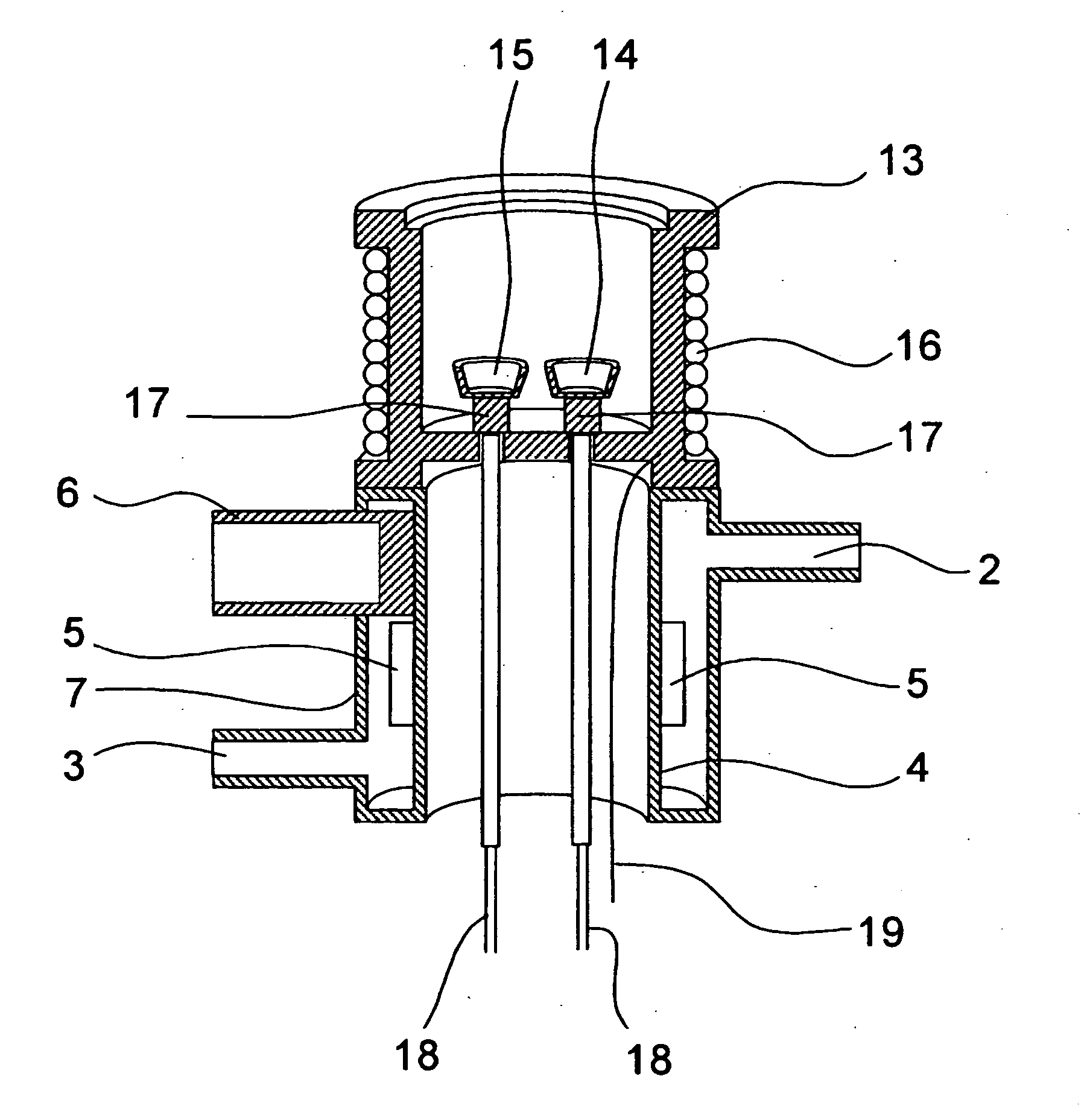
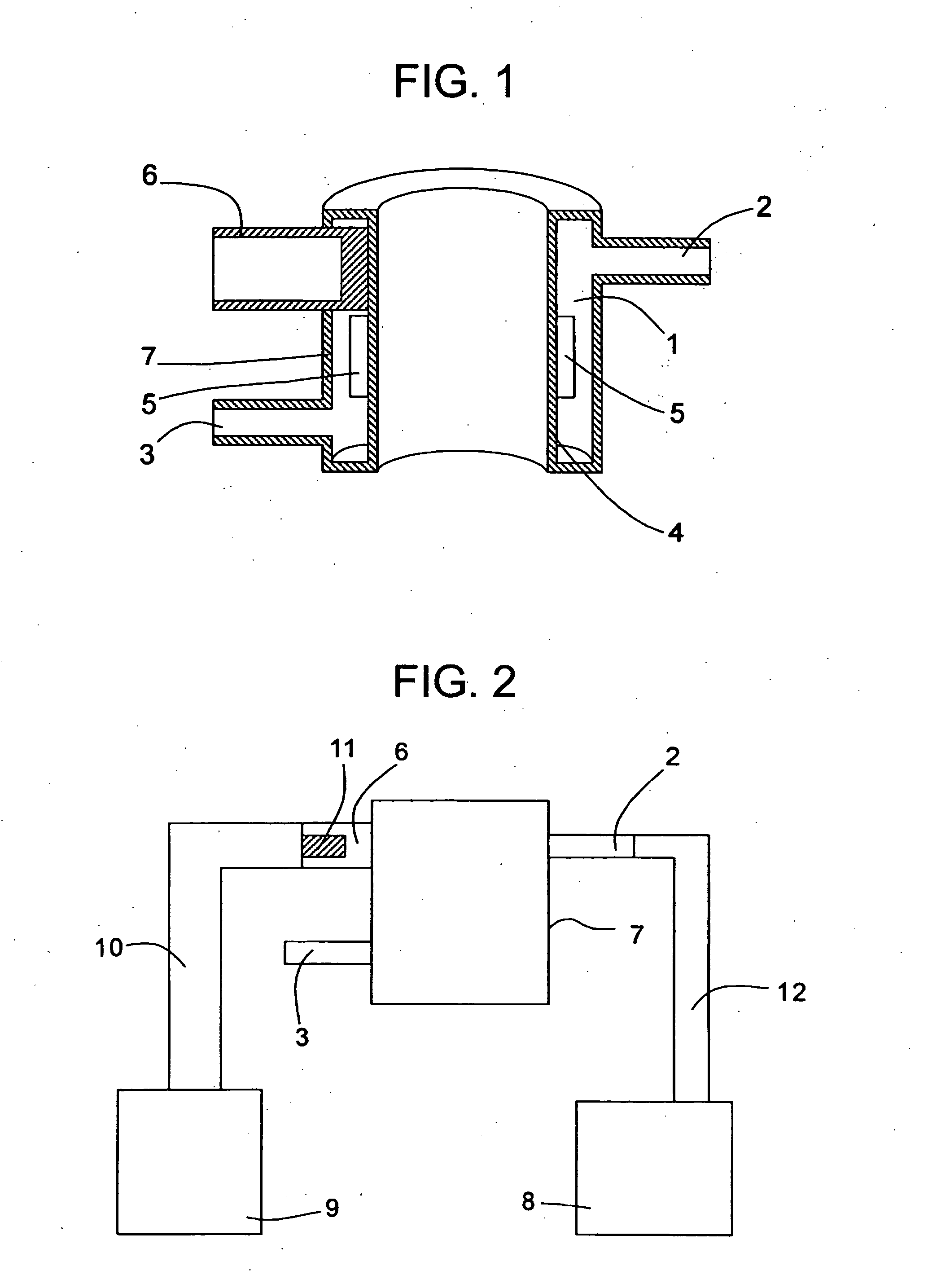
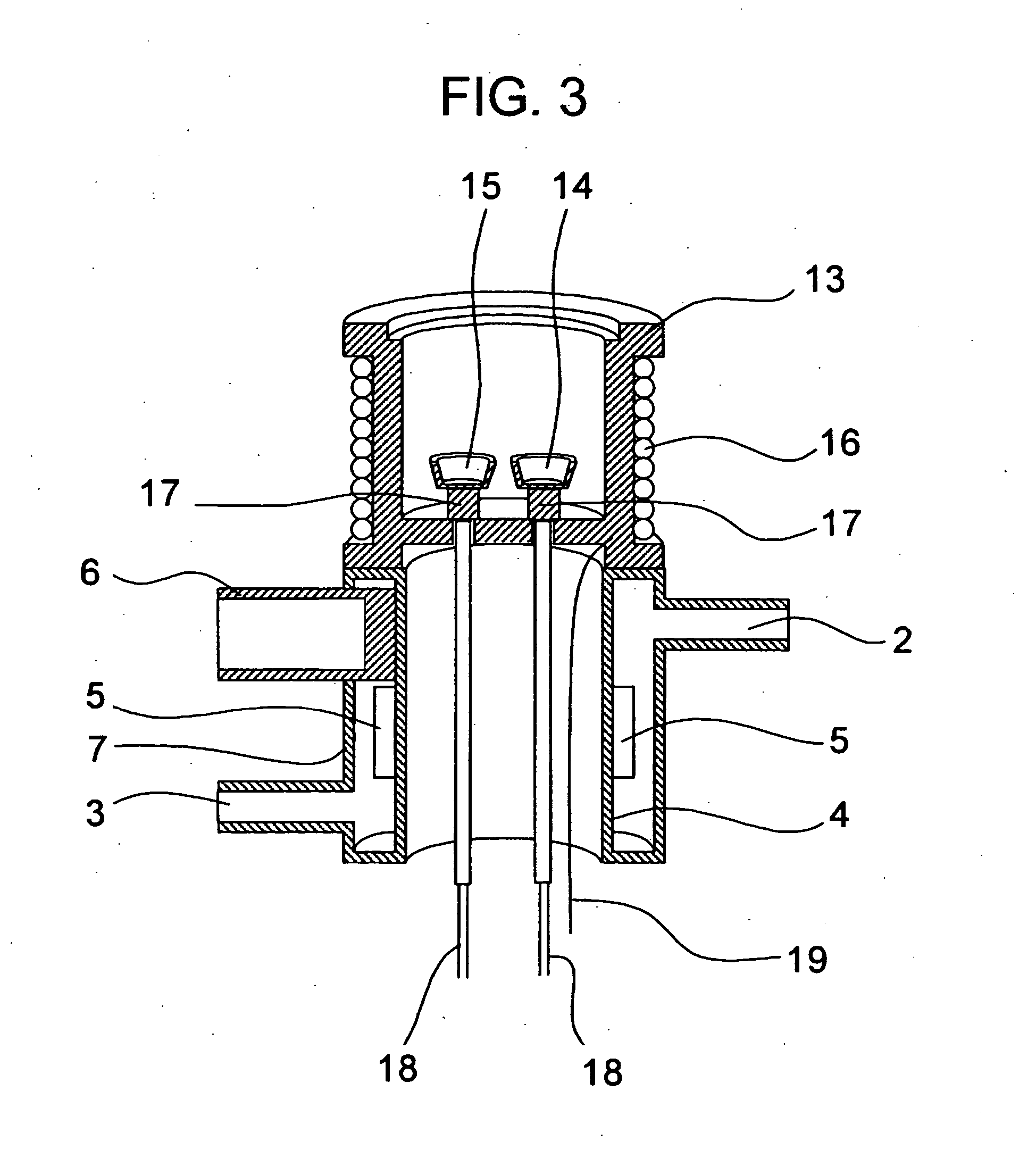
[0035]FIG. 1 shows a cooling mechanism used in a cooling device which can use a plurality of cooling means in combination.

[0036] As shown FIG. 1, the cooling mechanism is constituted of an annular hollow pipe and forms a cavity 1 therein. The cavity 1 is provided with a cooling gas inlet port 2 which allows the introduction of a cooling gas from a gas cooling device and a cooling gas discharge port 3 which allows the discharge of the cooling gas toward the outside. On an inner side of an inner wall 4 of the cooling device, a plurality of plate-like fins 5 is formed for enhancing the cooling efficiency.

[0037] An inner surface of the inner wall 4 of the cooling device has the structure in which a bottom surface of a cylindrical cooling head fixing member 6 of the electric cooling device is brought into contact with the inner surface of the inner wall 4 or the cooling head fixing member 6 is integrally formed with the inner wall 4 and hence, the head fixing member 6 is thermally conn...


PUM

PropertyMeasurementUnit
temperatureaaaaaaaaaa
thermal analyzeraaaaaaaaaa
thermalaaaaaaaaaa

Abstract

The present invention provides a thermal analyzer having a cooling device which can realize cooling of a specimen to a temperature equal to or below −100° C. by suppressing the consumption of gas also in performing rapid cooling. The cooling device includes a cooling gas inlet port and a cooling gas discharge port for a gas cooling device and an electric cooling device fixing mechanism, wherein the cooling device and the thermal analyzer are brought into thermal contact with each other. Due to such a constitution, it is possible to simultaneously connect the gas cooling device and the electric cooling device.

Description

BACKGROUND OF THE INVENTION [0001] 1. Field of the Invention [0002] The present invention relates to a cooling mechanism for cooling a heat sink in a thermal analyzer or the like, and a thermal analyzer such as a differential scanning calorimeter which utilizes the cooling mechanism. [0003] 2. Description of the Related Art [0004] A thermal analyzer such as a differential scanning calorimeter includes a heat sink which is under a temperature control, a specimen disposed in the inside of the heat sink, a reference material holder, a heater which heats the heat sink, and a cooling device which cools the heat sink. As such a cooling device, conventionally, there have been known a gas cooling device which performs cooling using a low-temperature gas which is obtained by evaporating liquefied nitrogen or the like (see, for example, Japanese Accepted Patent Publication Hei7(1995)-122619 (fourth column, FIG. 1), Japanese Accepted Patent Publication Hei7(1995)-65974 (fourth column, FIG. 1),...

Claims


Application Information

Patent Timeline
Patent Type & Authority Applications(United States)
IPC IPC(8): G01N25/00G01K17/00G01N25/48
CPCG01K17/00G01N25/4866G01N25/4826
Inventor NISHIMURA, SHINYA
Owner HITACHI HIGH TECH SCI CORP
Why Eureka
Try Eureka