Wireless communications apparatus and method using array antenna

a technology of array antennas and wireless communication, applied in diversity/multi-antenna systems, polarisation/directional diversity, differential interacting antenna combinations, etc., can solve the problems of incoming interference waves, inadequacies of uplink and downlink, and inability to produce transmission beam patterns based on the beam pattern of received signals

Inactive Publication Date: 2005-03-10
NTT DOCOMO INC
View PDF8 Cites 26 Cited by
  • Summary
  • Abstract
  • Description
  • Claims
  • Application Information

AI Technical Summary

Benefits of technology

The present invention is conceived to overcome the above-described problems, and it is an object of the present invention to provide a wireless communication technique for allowing an array antenna to produce a beam pattern with satisfactorily reduced interfering waves even in the asymmetric-traffic wireless communication environment.

Problems solved by technology

In this case, producing a transmission beam pattern based on the beam pattern of the received signal does not work.
In addition, the assumption that the directions of incoming interfering waves are almost the same on uplink and downlink is not appropriate any longer, because of the asymmetric traffic characteristic and difference in frequencies used.
Accordingly, it becomes difficult to reduce interfering waves and realize appropriate beam patterns on uplink and downlink (especially, on downlink).
However, because the received signal power obtained from each path is relatively small, the weighting error (which is the offset of the produced beam pattern from the optimum beam pattern due to thermal noise or other factors) becomes large.
Since the combined signal has relatively large power, the weighting error becomes small.
However, when the arriving direction varies among the paths greatly, namely, when the angle spread is large, then the receiving performance is degraded because the multiple paths are not distinguished.
Because of multipath fading, interfering waves cannot be reduced sufficiently, and a satisfactory beam pattern cannot be produced.

Method used


Image

  • Wireless communications apparatus and method using array antenna
  • Wireless communications apparatus and method using array antenna
  • Wireless communications apparatus and method using array antenna

Examples


first embodiment

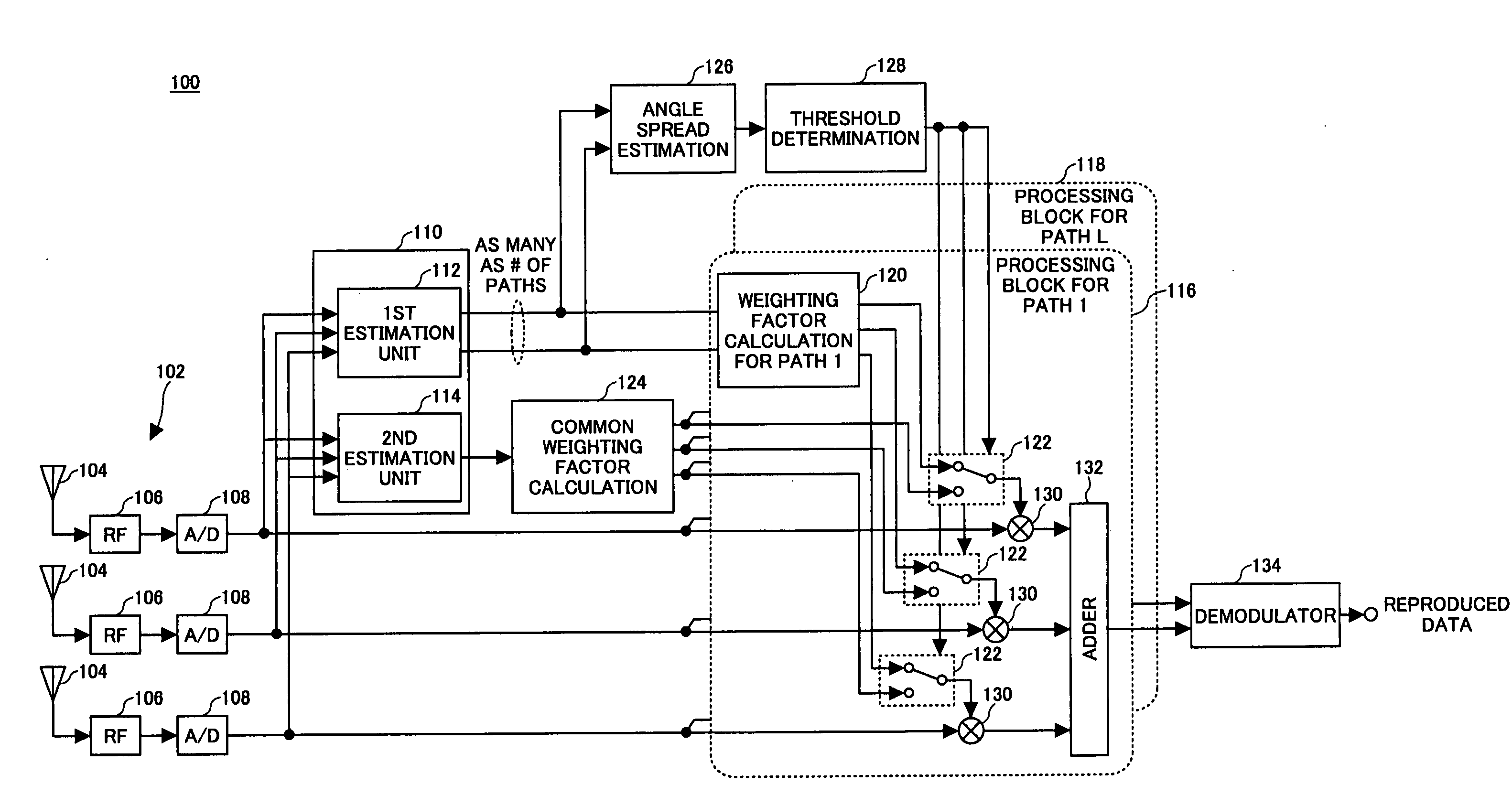
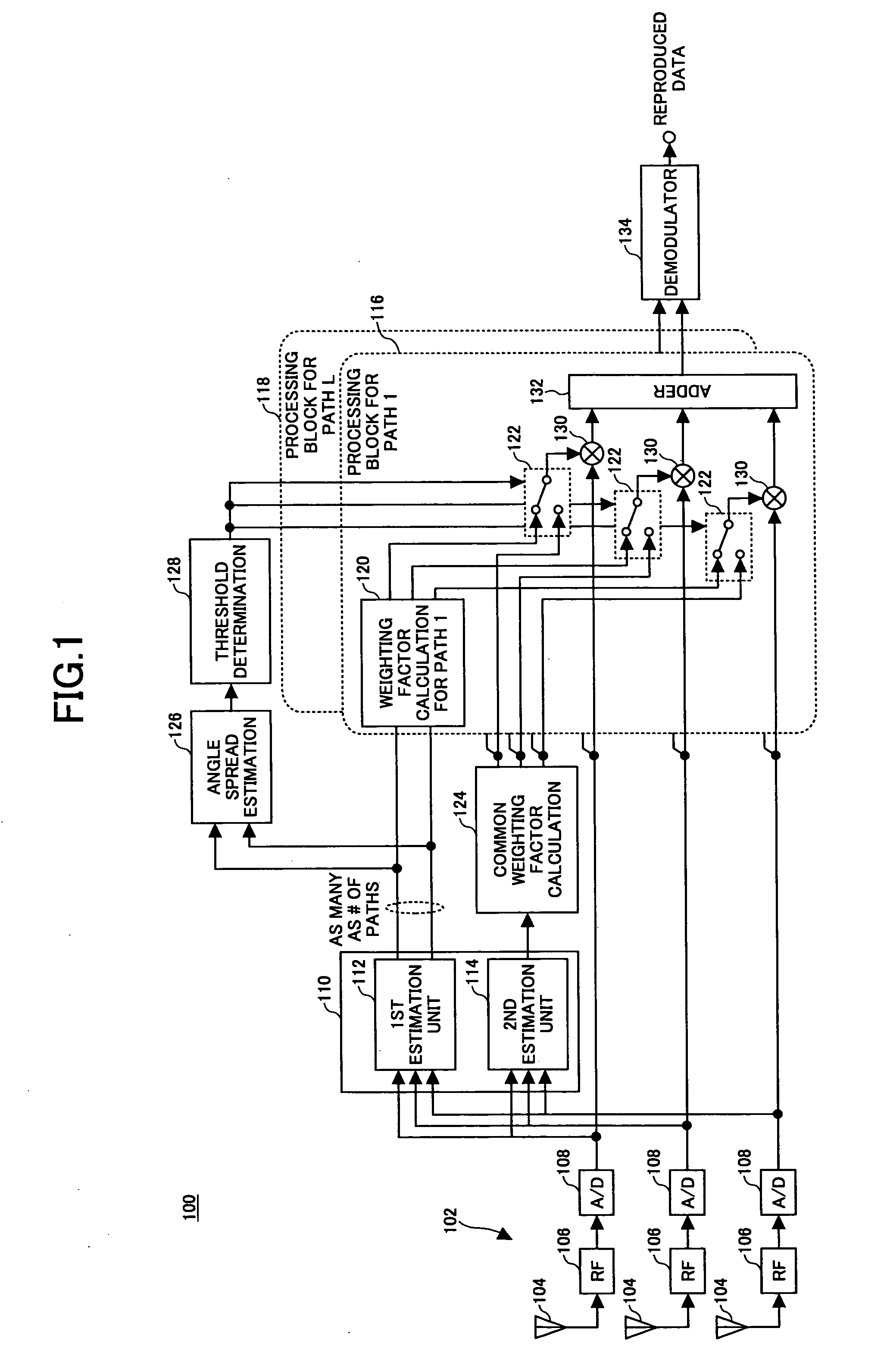
FIG. 1 is a functional block diagram of the main part of a wireless receiver 100 according to the invention. The wireless receiver 100 has an array antenna 102 with multiple antenna elements 104. In the drawing, only three antenna elements 104 are depicted for the sake of simplification; however, any suitable number of antenna elements can be employed. The antenna elements 104 are, for example, dipole antennas arranged in a line, an arc, or any suitable shape with an interval of half wavelengths, for example, between them. The size, the interval, and the shape of each of the antenna elements 104 are determined so as to realize an appropriate directivity (or beam pattern), and therefore, these factors are not limited to this example. Front end units 106 are connected to the respective antenna elements 104 to perform frequency conversion, bandwidth limitation, power amplification, and other front-end operations. The outputs of the front end units 106 are connected to the inputs of the...

second embodiment

FIG. 8 is a functional block diagram of a wireless communication apparatus according to the invention. The wireless communication apparatus has an array antenna 802 with multiple antenna elements 804. In the drawing, only three antenna elements 804 are depicted for the sake of simplification; however, any suitable number of antenna elements can be employed. The size, the interval, and the shape of each of the antenna elements 804 of the array antenna 802 are determined so as to realize an appropriate directivity (or beam pattern). Receiving front end units 806 are connected to the respective antenna elements 804 to perform frequency conversion, bandwidth limitation, power amplification, and other front-end operations for the received signal. The outputs of the receiving front end units 806 are connected to the inputs to the associated analog-to-digital converters 808. The digital outputs of the analog-to-digital converters 808 are supplied to each of baseband receiving units 810, 81...


PUM


Abstract

A wireless communication apparatus comprises an array antenna configured to receive a signal at multiple antenna elements; a DoA estimation unit configured to estimate directions of arrival of multiple paths contained in the received signal; an angle spread estimation unit configured to estimate an angle spread of the multiple paths; a first weighting calculation unit configured to estimate a common set of weighting factors for all the paths; a second weighting calculation unit configured to estimate an individual set of weighting factors for each of the multiple paths based on the estimated directions of arrival of the paths; a weighting unit configured to weight the received signal by multiplying the received signal by one of the common set of weighting factors or individual set of weighting factor; and a demodulator configured to demodulate the weighted signal.

Description

BACKGROUND OF THE INVENTION The present invention generally relates to a wireless communication technique, and more particularly, to a wireless communication apparatus and method using an array antenna. An adaptive array antenna technique is often used in wireless communication systems. In an adaptive array antenna, multiple dipole antennas are arranged in an array, and the weighting of each of the antennas is controlled in an adaptive manner so as to produce the optimum directivity (or beam pattern) for communication with counterpart equipment. In other words, the antenna gain is increased in the direction of desired signals (in which the counterpart equipment is located), while the antenna gain is made small in directions other than the desired direction. This arrangement allows the desired signals to be received, while reducing interfering waves. The conventional wireless communications systems with the adaptive array technique, such as a third generation mobile system based o...

Claims


Application Information

Patent Timeline
Patent Type & Authority Applications(United States)
IPC IPC(8): H01Q3/26H01Q21/00H04B7/06H04B7/08H04B7/10H04B7/26
CPCH01Q3/2605H04B7/0617H04B7/088H04B7/086H04B7/0695H01Q21/29
Inventor HIGUCHI, KENICHITAOKA, HIDEKAZUKATAOKA, TAKASHISAWAHASHI, MAMORU
Owner NTT DOCOMO INC
Why Eureka
Try Eureka