
Automatic gain control method for radio communication mobile station

Inactive Publication Date: 2005-03-10
LENOVO INNOVATIONS LTD HONG KONG
View PDF11 Cites 1 Cited by
  • Summary
  • Abstract
  • Description
  • Claims
  • Application Information

AI Technical Summary

Benefits of technology

[0025] In consideration of the above disadvantages, it is an object of the present invention to provide a new technique capable of setting an automatic gain control loop which can follow fading pitches having different periods with a relatively simple configuration.
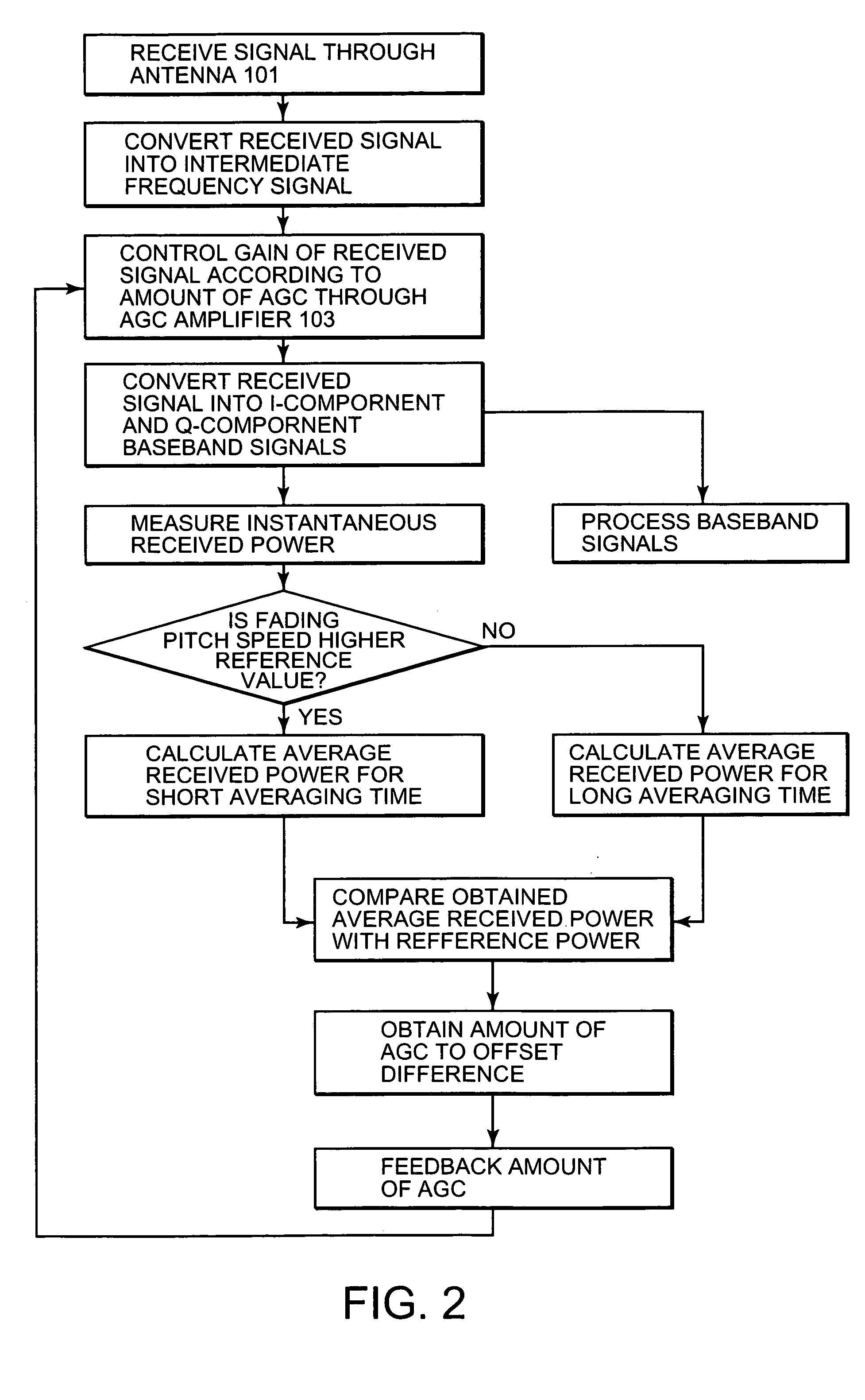
[0027] According to the method of the present invention, a fading pitch is measured on the basis of the power of a received signal, and averaging time required to calculate average received power used in controlling an AGC amplifier is changed. When the received signal power changes very strongly, namely, the fading pitch is high, the gain control of the AGC amplifier is performed at a high rate, thus allowing the gain control of the AGC amplifier to follow the change in received power due to fast fading. Consequently, the amplitudes of I-component and Q-component baseband signals obtained by orthogonal demodulation can be kept constant, thus preventing a degradation in receiver sensitivity.
[0028] The present invention further provides a radio communication mobile station having a fading pitch measuring device for measuring the fading pitch of a received signal. When the fading pitch is high, averaging time required to calculate average received power used to obtain an AGC signal is reduced, thus allowing the gain control of an AGC amplifier to follow a steep change in received signal power due to fast fading so that the amplitudes of I-component and Q-component baseband signals to be supplied to a baseband signal processor are always kept constant.
[0030] According to the method of the present invention, the fading pitch of a received signal is measured, and the measured fading pitch is compared to a reference value. If the measured fading pitch is higher than the reference value, averaging time required to calculate average received power is reduced. Even when the power of a received signal steeply changes due to fast fading, the gain control of an AGC amplifier can follow the steep change in received power, so that the respective amplitudes of I-component and Q-component baseband signals to be supplied to a baseband signal processor can always be kept constant. A degradation in receiver sensitivity can be prevented.

Problems solved by technology

In the conventional radio communication mobile station, however, under circumstances where the power of a received signal varies due to fast fading, the gain control of the AGC amplifier 503 cannot follow a steep change in received signal power, resulting in variations of the respective amplitudes of I-component and Q-component signals to be generated.
Disadvantageously, an error occurs in the received signal in the baseband signal processor 506.
Consequently, the gain control of the AGC amplifier 503 cannot follow a steep change in received signal power, resulting in a fluctuation in power of the I-component and Q-component baseband signals.
Unfortunately, the structure of the system is complicated.
Disadvantageously, the optimum automatic gain control loop cannot be set with respect to various fading periods.
However, in a case where the fading pitch of a signal received at the antenna is high because the corresponding radio communication mobile station moves at a high speed, when the gain of the AGC amplifier is controlled using calculated average received power per predetermined time, the average received power cannot follow a change in power due to fast fading.
Disadvantageously, an error occurs in the received signal.

Method used


Image

  • Automatic gain control method for radio communication mobile station
  • Automatic gain control method for radio communication mobile station
  • Automatic gain control method for radio communication mobile station

Examples


first embodiment

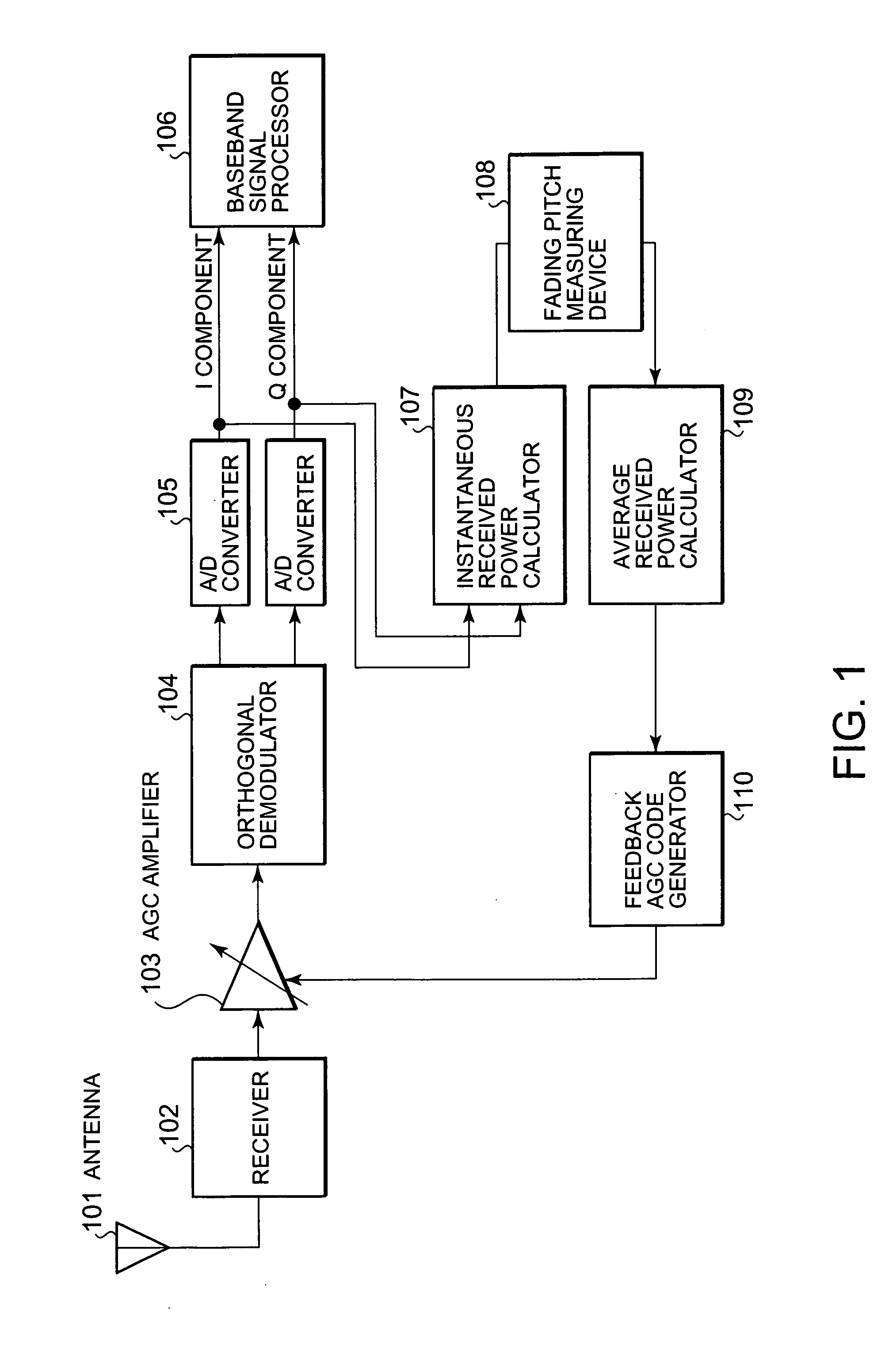
[0037]FIG. 1 is a block diagram of a radio communication mobile station according to the present invention.

[0038] The radio communication mobile station according to the present embodiment includes an antenna 101 for receiving a radio signal transmitted from a base station (not shown), a receiver 102 for performing radio signal processing, e.g., frequency-converting the received signal having a radio frequency bandwidth into a radio signal having an intermediate frequency bandwidth, an AGC amplifier 103 of which gain is controllable depending on the power of the received signal, an orthogonal demodulator 104 for performing orthogonal demodulation and frequency conversion to the intermediate frequency signal to produce I-component and Q-component baseband signals, analog-to-digital (AD) converters 105 for converting the I-component and Q-component baseband signals, that are analog, into digital signals, respectively, a baseband signal processor 106 for performing digital signal proce...

second embodiment

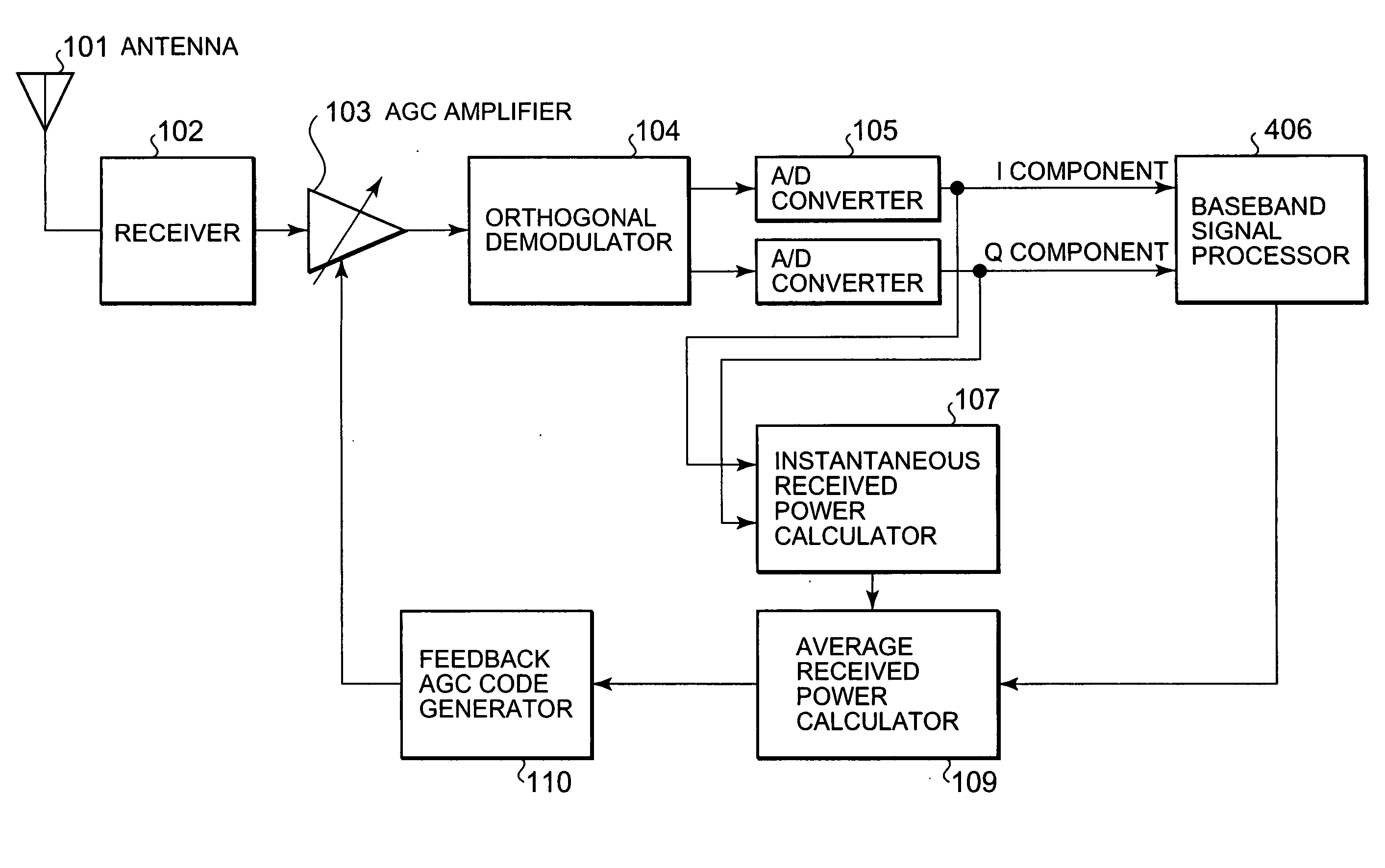
[0056]FIG. 4 is a block diagram of a radio communication mobile station according to the present invention. Referring to FIG. 4, the same components as those in FIG. 1 are designated by the same reference numerals.

[0057] According to the foregoing first embodiment, radio waves from the base station are received and the fading pitch thereof is then measured. Averaging time required to calculate the average received power used in controlling the AGC amplifier is changed depending on the measured fading pitch. According to the present embodiment, a base station transmits fading pitch information. A radio communication mobile station receives the fading pitch information and changes averaging time according to the received fading pitch information. The averaging time is required to calculate average received power used in controlling the gain of an AGC amplifier.

[0058] Generally, a fading pitch is high in a specific location such as an expressway or a high-rise community. In such an ar...


PUM


Abstract

A signal transmitted from a base station is received by a receiver. The received signal is supplied to an AGC amplifier and is then supplied to a demodulator, so that the signal is demodulated into baseband signals. The baseband signals are supplied to a baseband signal processor. The baseband signals are also processed through an instantaneous received power calculator, an average received power calculator, and a feedback AGC code generator to produce an AGC signal. The gain of the AGC amplifier is controlled based on the AGC signal. A fading pitch measuring device measures a fading pitch from the instantaneous power calculated by the instantaneous received power calculator. The average received power calculator changes averaging time required to calculate average received power depending on the measured fading pitch.

Description

BACKGROUND OF THE INVENTION [0001] 1. Field of the Invention [0002] The present invention relates to automatic gain control used in radio communication mobile stations and, more particularly, to an automatic gain control method for realizing stable reception characteristics against a change in fading period. [0003] 2. Description of the Related Art [0004] Generally, automatic gain control (AGC) used in radio communication mobile stations is performed so as to keep constant the amplitude of an in-phase (I) component signal and that of a quadrature (Q) component signal supplied from a radio unit to a baseband signal processing unit in a radio communication mobile station. FIG. 5 is a block diagram of an example of the arrangement of components for AGC in a conventional radio communication mobile station. [0005] Referring to FIG. 5, the radio communication mobile station includes an antenna 501 for receiving a signal transmitted from a base station, a receiver 502 for radio signal proc...

Claims


Application Information

Patent Timeline
IPC IPC(8): H03G3/20H03D3/00H03G3/30H04B1/16
CPCH03D3/007
Inventor FURUYA, TOMOKI
Owner LENOVO INNOVATIONS LTD HONG KONG
Learn More