System and method for 3D photography and/or analysis of 3D images and/or display of 3D images

a technology of system and method, applied in the field of 3d (three-dimensional) images, can solve the problems of increasing the vertical distortion increasing the cost of the two cameras, and affecting the quality of the image, so as to achieve the effect of efficient generation

Inactive Publication Date: 2005-03-10
MAYER YARON +1
View PDF10 Cites 143 Cited by
  • Summary
  • Abstract
  • Description
  • Claims
  • Application Information

AI Technical Summary

Benefits of technology

[0008] The present invention tries to solve the above problems by using a 3D camera which can automatically adjust in a way that solves the zoom problem, and providing a solution also for filming smaller models. Similar methods can be used for example for a much better stereoscopic telescope with or without a varying zoom factor. In addition, the patent shows various ways to generate efficiently a 3D knowledge of the surrounding space, which can be used also for example in robots for various purposes.

Problems solved by technology

On the other hand, with very close images that are later displayed to the user as jumping in front of the screen, the above mentioned vertical distortions created by the two cameras might be further increased if the eyes again try to converge on the illusion of the image.
(Another possible variation is, instead of or in addition to changing also the angle during zoom, using wider angle lenses or for example fish eye lenses and taking a different part of the image, but this is more expensive and more problematic since also a larger areas CCD is needed in that case and such lenses can cause various distortions).
(Another possible variation is that the sensor in the middle is not needed and the infrared detectors coupled to one or two of the lenses are used also for determining the distance, but that might be less reliable if for example the lenses temporarily loose the alignment).
However, the above applications ignore the possibility that a similar problem might exist when photographing or filming images with only 3 CCDs (one for each of the 3 primary colors), so that part of the color information is lost because it cannot be represented properly by only 3 primary color CCDs.
The opposite extrapolation can be used for example in a home 3D video camera, that allows for example a zoom factor of up to 1:10, but it is undesired that the lenses can move apart up to 65 cm, unlike the above discussed movie camera.
Another possible variation is to add even new side-view details by guessing how the missing part should look like, for example by using AI that can identify standard objects, and / or for example by assuming symmetry of the two sides, and / or for example by using the info from the movement of the objects or of the camera, if such a movement previously revealed more information about the missing side-views, but that might be more complicated and less reliable.
Even for a screen that uses a different focal point for each pixel preferably also the original two (or more) images for each frame are used, since otherwise there will still be the problem that viewing for example a supposedly closer image will still not reveal the appropriate side-views.
However, dealing with the in-between situation is less important since the problem occurs only in a small percent of the possible user positions.

Method used


Image

  • System and method for 3D photography and/or analysis of 3D images and/or display of 3D images
  • System and method for 3D photography and/or analysis of 3D images and/or display of 3D images
  • System and method for 3D photography and/or analysis of 3D images and/or display of 3D images

Examples


Embodiment Construction

[0020] All of descriptions in this and other sections are intended to be illustrative examples and not limiting.

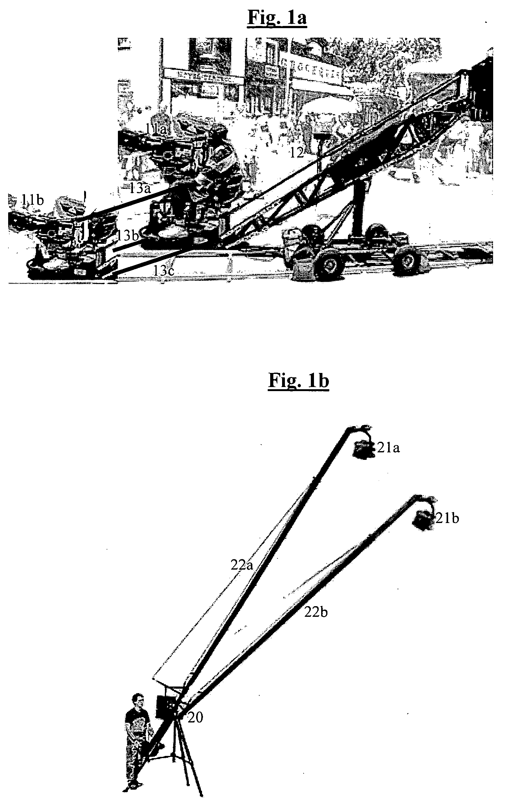
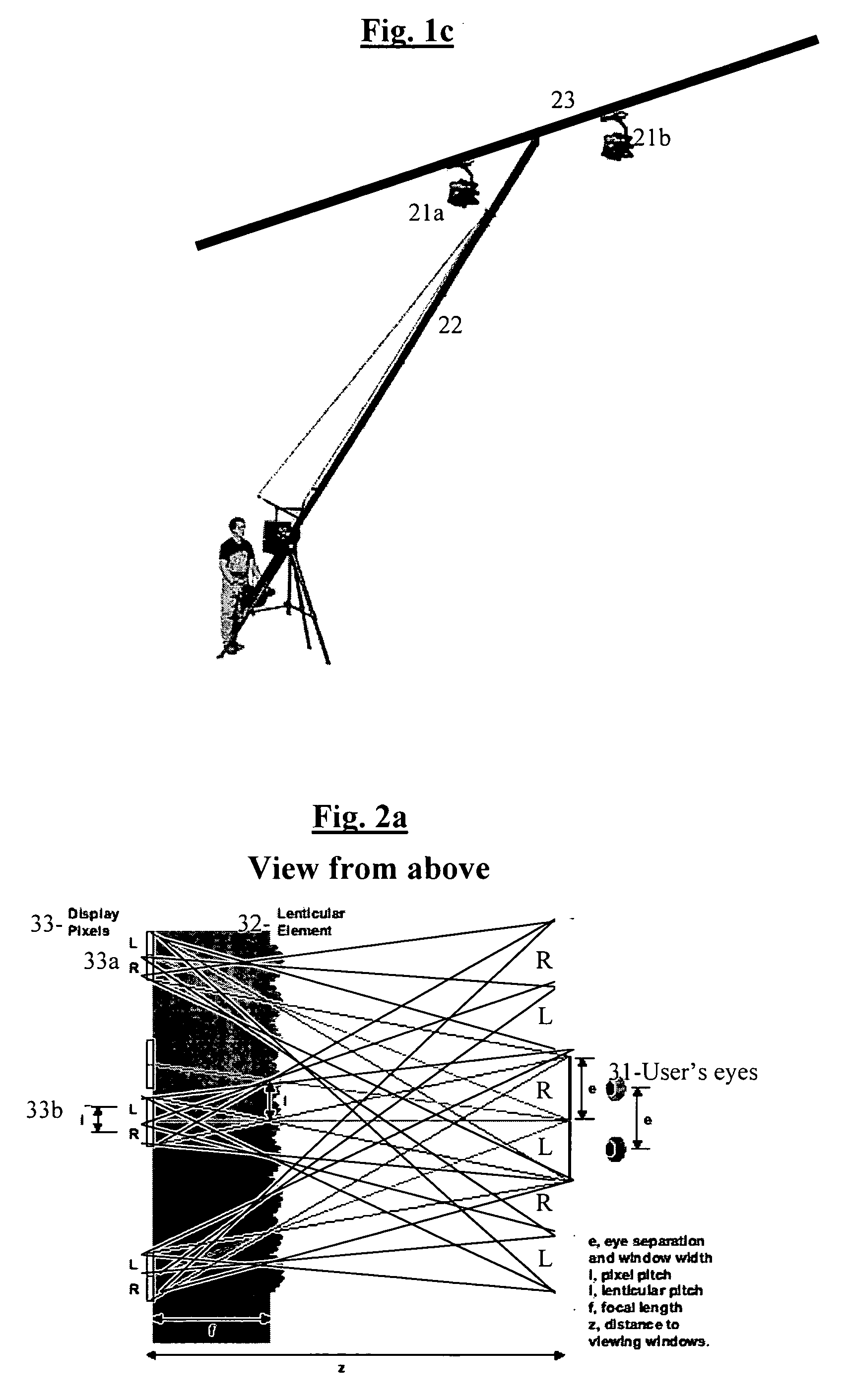
[0021] Referring to FIGS. 1a-c we show an illustration of a few preferable ways for automatically changing the distance and / or angles between the lenses of the two (or more) cameras. For solving the zoom problem, preferably the camera is based on two or more separate units (which can be for example two or three or more parts of the same camera, or 2 or 3 or more separate cameras), which are preferably coordinated exactly by computer control, so that each two (or more) frames are shot at the same time, and focus and / or zoom changes and / or any movements of the two parts are well correlated. So for example the operator can change the focus in one of the cameras for example by mechanical rotation or for example by moving an electronic control and preferably instantly the same movement or change is preferably electronically transferred also to the other camera or cameras. When...


PUM


Abstract

When 3D viewing means become much more available and common, it will be very sad that the many great movies that exist today will be able to be viewed in 3D only through limited and partial software attempts to recreate the 3D info. Films today are not filmed in 3D due to various problems, and mainly since a normal stereo camera could be very problematic when filming modern films, since for example it does not behave properly when zooming in or out is used, and it can cause many problems when filming for example smaller scale models for some special effects. For example, a larger zoom requires a correspondingly larger distance between the lenses, so that for example if a car is photographed at a zoom factor of 1:10, the correct right-left disparity will be achieved only if the lenses move to an inter-ocular distance of for example 65 cm instead of the normal 6.5 cm. The present invention tries to solve the above problems by using a 3D camera which can automatically adjust in a way that solves the zoom problem, and provides a solution also for filming smaller models. The angle between the two lenses is preferably changed according to the distance and position of the object that is at the center of focus, and changing the zoom affects automatically both the distance between the lenses and their angle, since changing merely the distance without changing the convergence angle would cause the two cameras to see completely different parts of the image. The patent also shows that similar methods can be used for example for a much better stereoscopic telescope with or without a varying zoom factor. In addition, the patent shows various ways to generate efficiently a 3D knowledge of the surrounding space, which can be used also for example in robots for various purposes, and also describes a few possible improvements in 3d viewing.

Description

[0001] This Patent application claims priority from Israeli application 155525 of Apr. 21, 2003, hereby incorporated by reference in its entirety. BACKGROUND OF THE INVENTION [0002] 1. Field of the Invention [0003] The present invention relates to 3D (three-dimensional) images, and more specifically to a system and method for 3D photography and / or analysis of 3D images and / or display of 3D images, for example for filming 3D movies of high quality or for allowing robots to have a better conception of their 3D surroundings. [0004] 2. Background [0005] There have been many attempts in the prior art to create display methods for 3D still images or movies, and there have been stereoscopic cameras based on photographing or filming with two parallel lenses that are at approximately the same distance from each other as human eyes, so that a separate image for each eye can be captured. The two separate images can then be displayed each to the appropriate eye for example by using two separate...

Claims


Application Information

Patent Timeline
Patent Type & Authority Applications(United States)
IPC IPC(8): G03B21/18G03B35/00G06K9/00H04N13/239
CPCG03B21/18G03B35/08H04N13/0296H04N13/0246H04N13/0239H04N13/246H04N13/296H04N13/239
Inventor MAYER, YARONGADASSI, HAIM
Owner MAYER YARON
Why Eureka
Try Eureka