Forming method for composites

a composite material and forming method technology, applied in dough shaping, manufacturing tools, food shaping, etc., can solve the problems of large amount of hand labor for forming complex contoured composite structures, limited success of methods on very thick laminates or more complex shapes, and inability to meet the needs of complex shapes and complex shapes. , to achieve the effect of reducing or eliminating out-of-plane fiber buckling and minimizing the shear zon

Active Publication Date: 2005-03-10
THE BOEING CO
View PDF28 Cites 19 Cited by
  • Summary
  • Abstract
  • Description
  • Claims
  • Application Information

AI Technical Summary

Benefits of technology

[0014] The present invention minimizes the shear zone where plies and the composite laminate charge slide past one another during the forming process thereby reducing or eliminating out-of-plane fiber buckling.

Problems solved by technology

Historically, complex contoured composite structures have entailed extensive hand labor to form prior to curing.
However, manual lay-up of pre-preg plies or dry fabric is time-consuming.
However, this method has met with limited success on very thick laminates or more complex shapes.
Vacuum bag drape forming of such parts often results in wrinkling of the plies.
Similarly, on long flange parts, slip resistance between the plies during bending becomes too great, and inner plies buckle.
As the composite pre-preg charge is bent over the mandrel, if the length of the flange is too long or slip resistance between the plies is too great, out-of-plane-buckling of the laminate will occur.
Current state-of-the-art drape forming techniques using vacuum bags have not been able to control the stress state and shear forces occurring during the composite forming process.
As a result, complex contoured shapes are typically manufactured by ply-by-ply hand lay-up techniques.
However, such methods have encountered the same difficulties in preventing out-of-plane buckling of the laminate during the forming process.
This creates a tendency for out-of-plane buckling, especially with thick laminates, long flange lengths, contoured parts, joggles or parts with inflections.

Method used


Image

  • Forming method for composites
  • Forming method for composites
  • Forming method for composites

Examples


Embodiment Construction

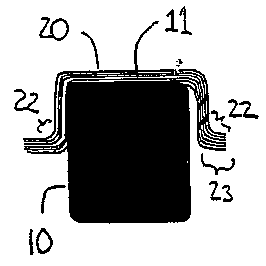
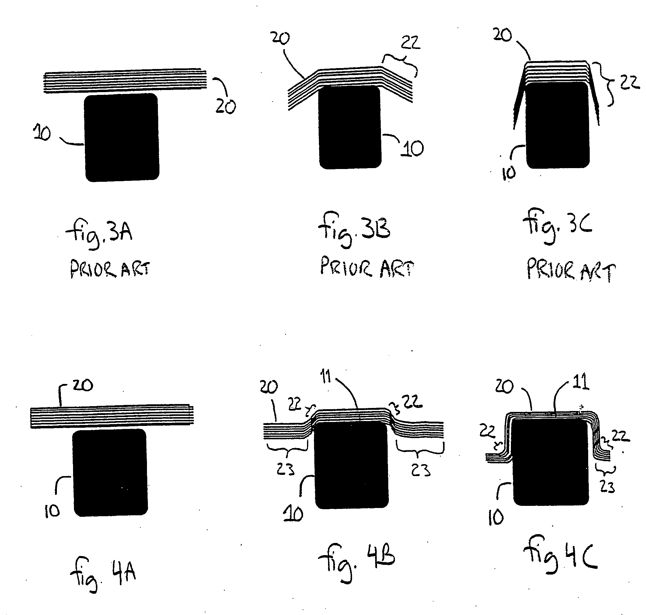
[0026] By way of overview, a method for forming composite materials is provided. A composite charge wider than a first surface of a mandrel is positioned across the first surface of the mandrel. The portion of the composite charge overhanging the first surface of the mandrel is supported and urged against the mandrel while the unbent portion of the composite charge is supported substantially parallel to the first surface of the mandrel. The invention also provides a system for forming composite materials. A compression mold of forming bladders and heater plates forms a composite charge over a mandrel and supports the unbent portions of the composite charge during forming substantially parallel to the upper surface of the mandrel. The present invention thus minimizes the shear zone where plies in the composite laminate charge slide past one another during the forming process thereby reducing or eliminating out-of-plane fiber buckling.

[0027]FIGS. 4A, 4B, and 4C are progressive cross-...


PUM

PropertyMeasurementUnit
angleaaaaaaaaaa
angleaaaaaaaaaa
temperatureaaaaaaaaaa

Abstract

A method for forming composite materials is presented, including providing a composite charge wider than a first surface of a mandrel, and positioning the composite charge across the first surface of the mandrel. The portion of the composite charge overhanging the first surface of the mandrel is supported and urged against the mandrel while supporting the unbent portion of the composite charge substantially parallel to the first surface of the mandrel. The invention also provides a system, using a compression mold of forming bladders and heater plates, to form a composite charge over a mandrel, while supporting the unbent portions of the composite charge during forming substantially parallel to the upper surface of the mandrel. The present invention minimizes the shear zone where plies in the composite laminate charge slide past one another during the forming process reducing or eliminating out-of-plane fiber buckling.

Description

RELATED APPLICATIONS [0001] This application is related to concurrently filed patent application entitled, “Composite Spar Drape Forming Machine,” and bearing Attorney Docket No. BOEI-1-1069, the contents of which are hereby incorporated by this reference.FIELD OF THE INVENTION [0002] This invention relates generally to forming composite materials, and, more specifically, to forming shaped composite parts. BACKGROUND OF THE INVENTION [0003] Formed composite parts are commonly used in applications, such as aircraft and vehicles, where light weight and high strength are desired. These applications typically utilize complex contoured parts or channels which must be formed and then cured. Historically, complex contoured composite structures have entailed extensive hand labor to form prior to curing. Typically, pre-impregnated composite fiber plies (“pre-pregs”) such as epoxy impregnated carbon fiber laminates are laid by hand over a shaped form or mandrel. Then the part is cured, often ...

Claims


Application Information

Patent Timeline
Patent Type & Authority Applications(United States)
IPC IPC(8): B29C43/12B29C43/18B29C43/36B29C70/44B29C70/46
CPCB29C43/12B29C43/18B29C43/3642Y10T428/24198B29C70/46B29C70/56Y10T428/24628B29C70/44B29C70/541
Inventor WILLDEN, KURTIS S.VAN WEST, BARRY P.HARRIS, CHRISTOPHER G.
Owner THE BOEING CO
Why Eureka
Try Eureka