

Fiber-reinforced composite material and method for production thereof
- Summary
- Abstract
- Description
- Claims
- Application Information
AI Technical Summary
Benefits of technology
Problems solved by technology
Method used
Image

Examples
example 1
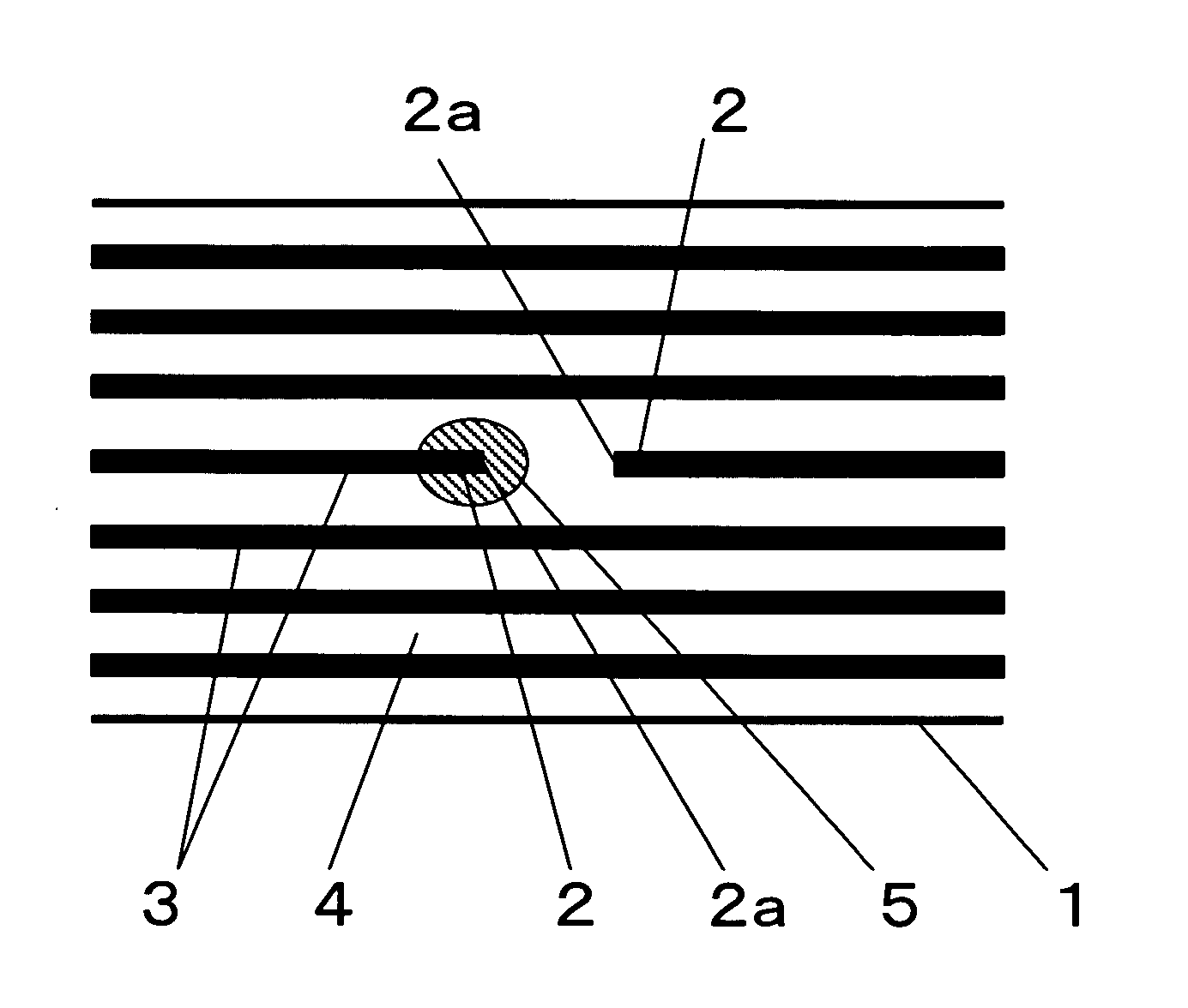
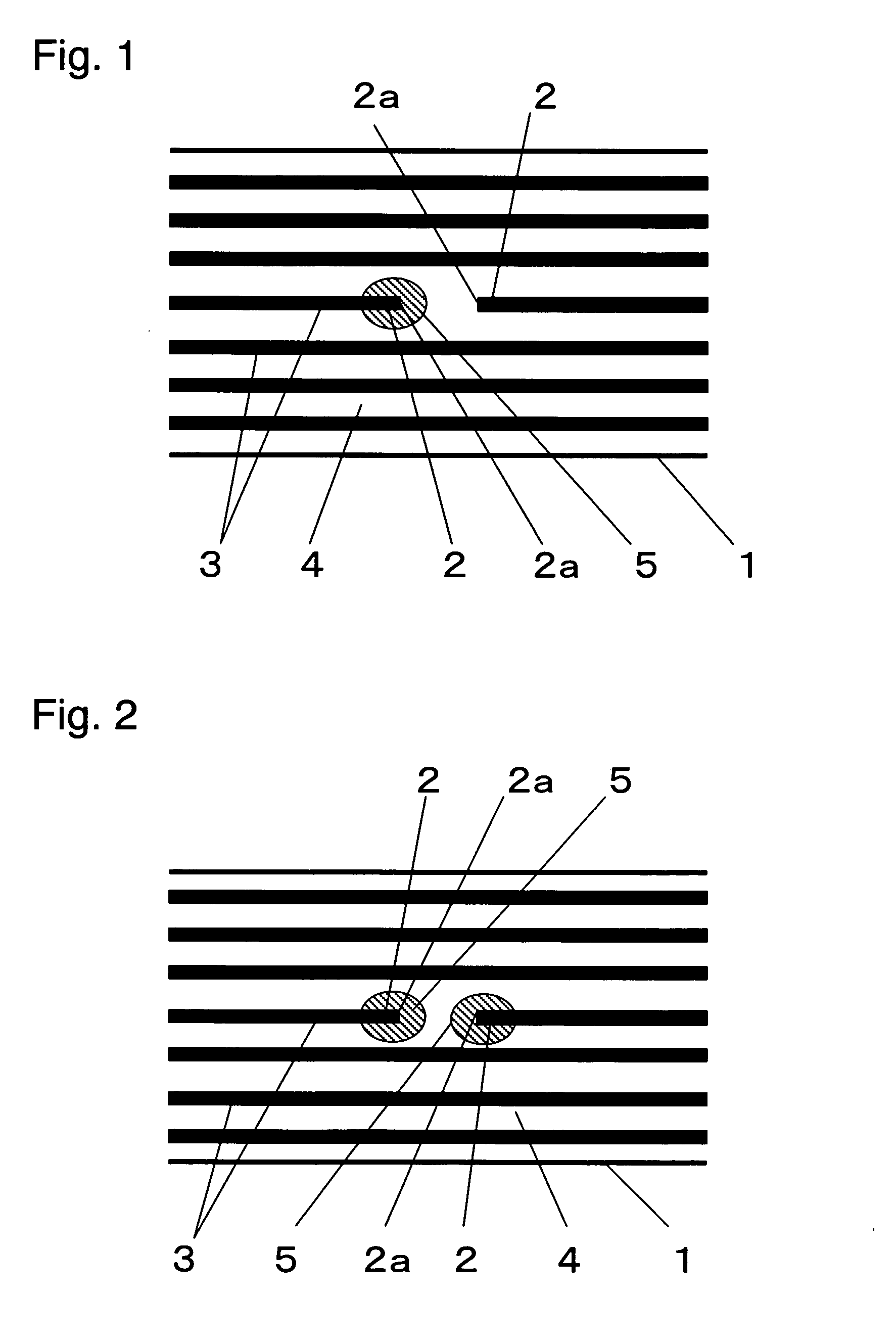
[0084] Seven plies of a unidirectional carbon fiber prepreg (containing 59 vol % of carbon fibers) containing carbon fibers (elastic modulus: 235 GPa, strength: 4.9 GPa, fiber diameter: 8 μm) as the reinforcing fibers 3 and an epoxy resin (elastic modulus: 3.5 GPa, elongation: 5%, strength: 80 GPa, fracture toughness value: 80 J / m2) as the matrix resin 4 were laminated in one direction, to prepare a fiber-reinforced composite material 1. In this case, the central one ply of the seven plies was cut in the direction (width direction) perpendicular to the fiber direction of the reinforcing fibers 3 using a cutter, to form fiber ends 2a, and a second resin 5 was made to adhere to the fiber ends 2a over a length of 0.5 mm. The second resin 5 was a nylon resin (elastic modulus: 1.8 GPa, elongation: 40%, strength: 40 MPa, fracture toughness value: 180 J / m2), and it was made to adhere to near the fiber end portions 2 in a fused state. From the obtained composite material 1, a tensile specim...
example 2
[0087] A fiber-reinforced composite material 1 was produced as described for Example 1, except that a mixture consisting of 95 parts by weight of the same epoxy resin as used in Example 1 and 5 parts by weight a polyether sulfone resin (PES) was used as the second resin 5, and that the adhering length was 0.3 mm. A tensile specimen was prepared as described in Example 1. As a result of a tensile test, the strength was 2,440 MPa. The weight of the specimen was 40 g. The elastic modulus, elongation and strength of the second resin 5 measured according to JIS K 7113 were respectively 2.5 GPa, 5% and 60 MPa, and the fracture toughness value of the second resin 5 measured based on ASTM E399 (Compact Test Standard) was 210 J / m2.
example 3
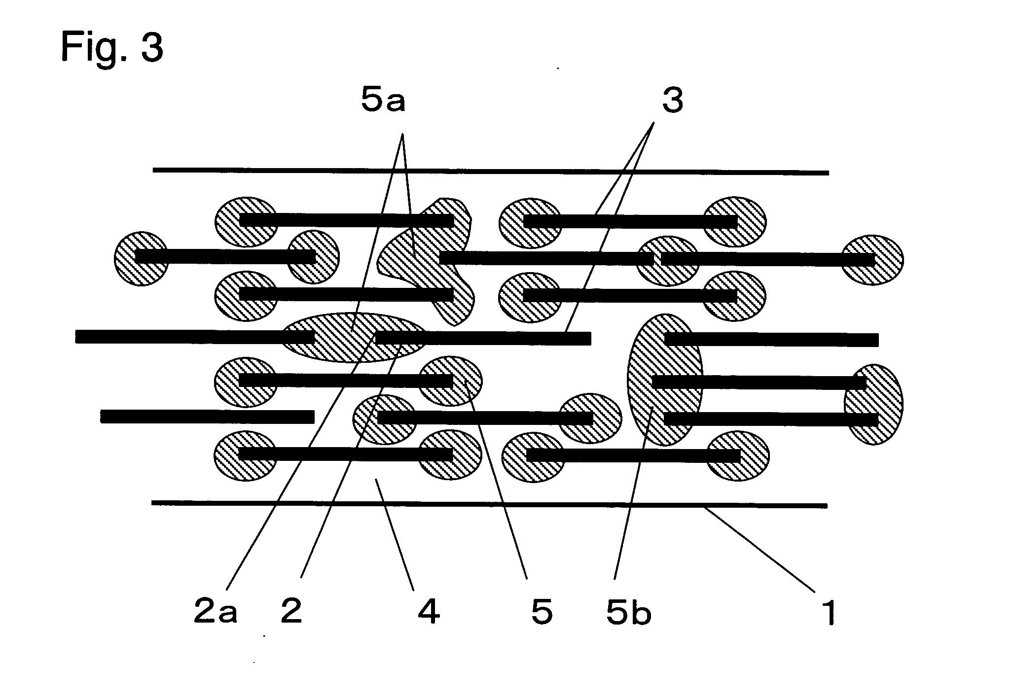
[0088] A carbon fiber bundle consisting of 240,000 carbon fibers (elastic modulus: 240 GPa, strength: 5.0 GPa, fiber diameter: 7 μm) was cut to have a length of 24 to 25 mm using a rotary cutter, to produce a short carbon fiber bundle. The same nylon resin (second resin 5) as used in Example 1 was made to adhere to both the ends of the obtained short carbon fiber bundle in length ranges of 0.5 to 1 mm from the fiber ends 2a in a fused state. The short carbon fiber bundle having the second resin 5 adhering to it was dispersed at random on a vinyl ester resin film, to produce an SMC sheet (fiber areal weight: 1,200 g / m2). Two such SMC sheets were overlaid, and the laminate was pressurized (50 atmospheric pressure) and heated (110° C.) for being molded in a box-shaped mold (150 mm×150 mm, 20 mm deep) installed in a press. During the molding, the reinforcing fibers in the SMC were virtually uniformly spread, and a box-shaped short carbon fiber-reinforced composite material 1 having a th...
PUM
| Property | Measurement | Unit |
|---|---|---|
| Fracture toughness | aaaaa | aaaaa |
| Diameter | aaaaa | aaaaa |
| Shape | aaaaa | aaaaa |
Abstract
Description
Claims
Application Information