

Probe head for coordinate measuring machines
a technology of coordinate measuring machine and probe head, which is applied in the direction of measurement gauge, error compensation/elimination, instruments, etc., can solve the problems of large demands on the control of the coordinate measuring machine, large measurement force, and inability to achieve high contact speed, etc., and achieve high precision
- Summary
- Abstract
- Description
- Claims
- Application Information
AI Technical Summary
Benefits of technology
Problems solved by technology
Method used
Image

Examples
Embodiment Construction
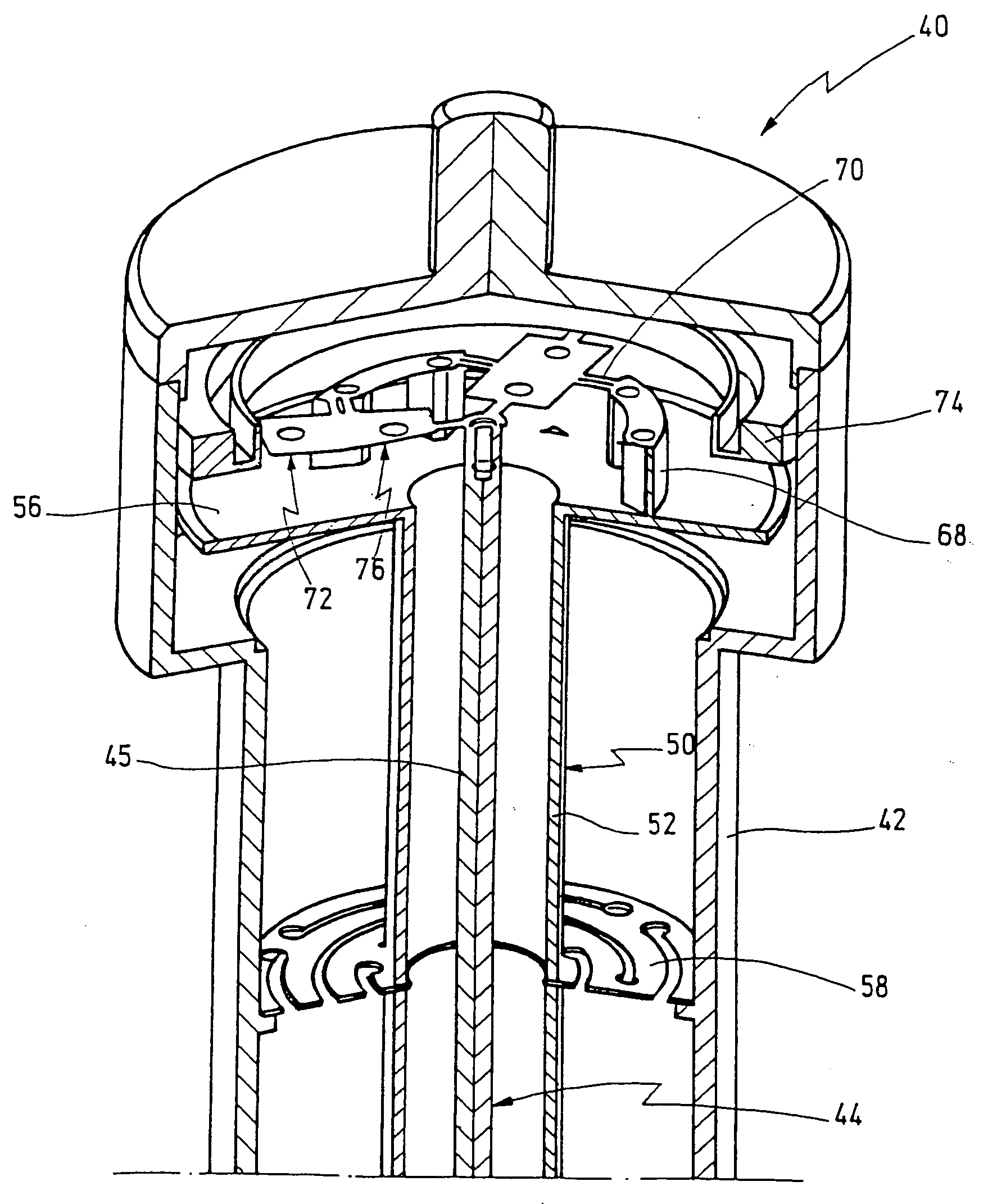
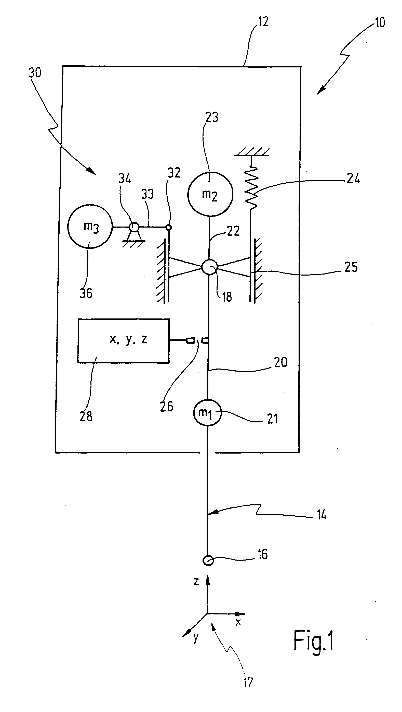
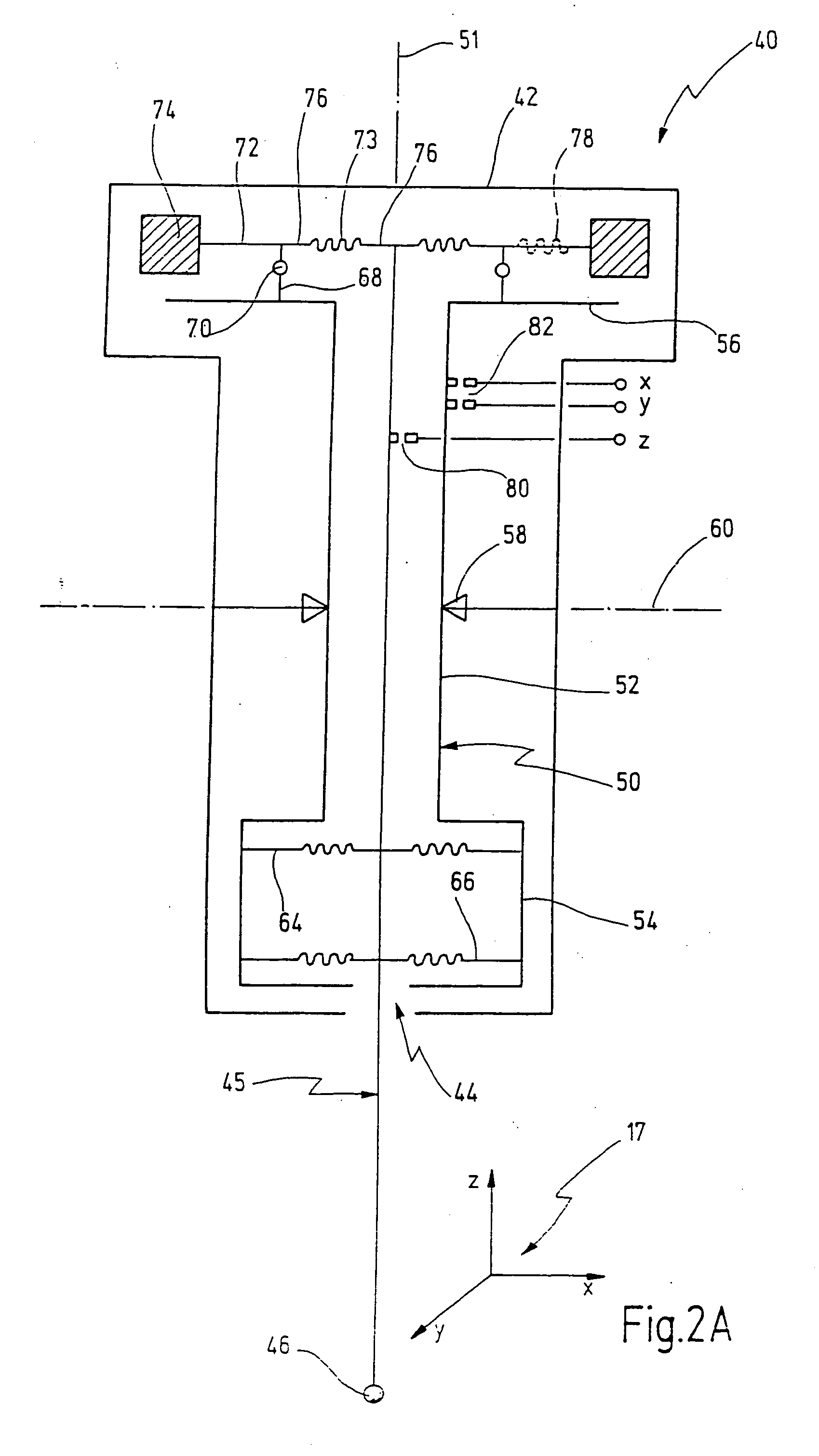
[0067] A probe head for a coordinate measuring machine is denoted overall by 10 in FIG. 1. The probe head 10 comprises a housing 12, in which a feeler device 14 is located. A tip 16 is located at the free end of the feeler device 14. The feeler device 14 is suspended such that the tip 16 can move along the three axes x, y and z of a Cartesian coordinate system 17.
[0068] For this purpose, the feeler device 14 is suspended at one end in a bearing 18. The bearing 18 is a cardanic bearing, the term “cardanic” being understood in the present context to mean that the tip 16 can execute a movement in the x-y plane, whereas a movement in the z-direction is not possible.
[0069] The feeler device 14 is subdivided into a lower portion 20 below the bearing 18, the weight 21 of which is symbolized by a mass m1, and an upper portion 22 above the bearing 18, the weight 23 of which is characterized by a mass m2.
[0070] The arrangement is made in this case such that the centroid of the masses m1 an...
PUM
 Abstract
Description
Claims
Application Information