Leak tester

a leak tester and tester technology, applied in the field of leak testers, can solve problems such as failure to automate leak testing, constant manual operation, and failure to detect leakage in electrical elements such as optical fibers or ccds

Inactive Publication Date: 2005-03-17
OLYMPUS CORP
View PDF18 Cites 92 Cited by
  • Summary
  • Abstract
  • Description
  • Claims
  • Application Information

AI Technical Summary

Benefits of technology

FIG. 9 is a diagram showing an example (1) of the configuration of a pulsation suppressing section 46.
F

Problems solved by technology

In this case, if a pin hole or a connection in the endoscope is loose, a liquid such as water or a disinfectant may enter the endoscope during washing or disinfection to cause a failure in an electric element such as an optical fiber or a CCD.
However, this method requires a human operator to execute visual

Method used


Image

  • Leak tester
  • Leak tester
  • Leak tester

Examples


first embodiment

the present invention will be described below with reference to the drawings. The first embodiment relates to a leak tester using a pressurized gas supplied by, for example, a cylinder.

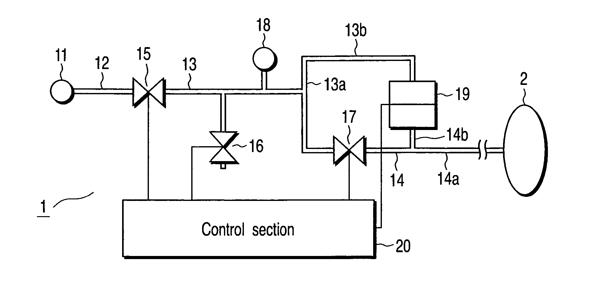
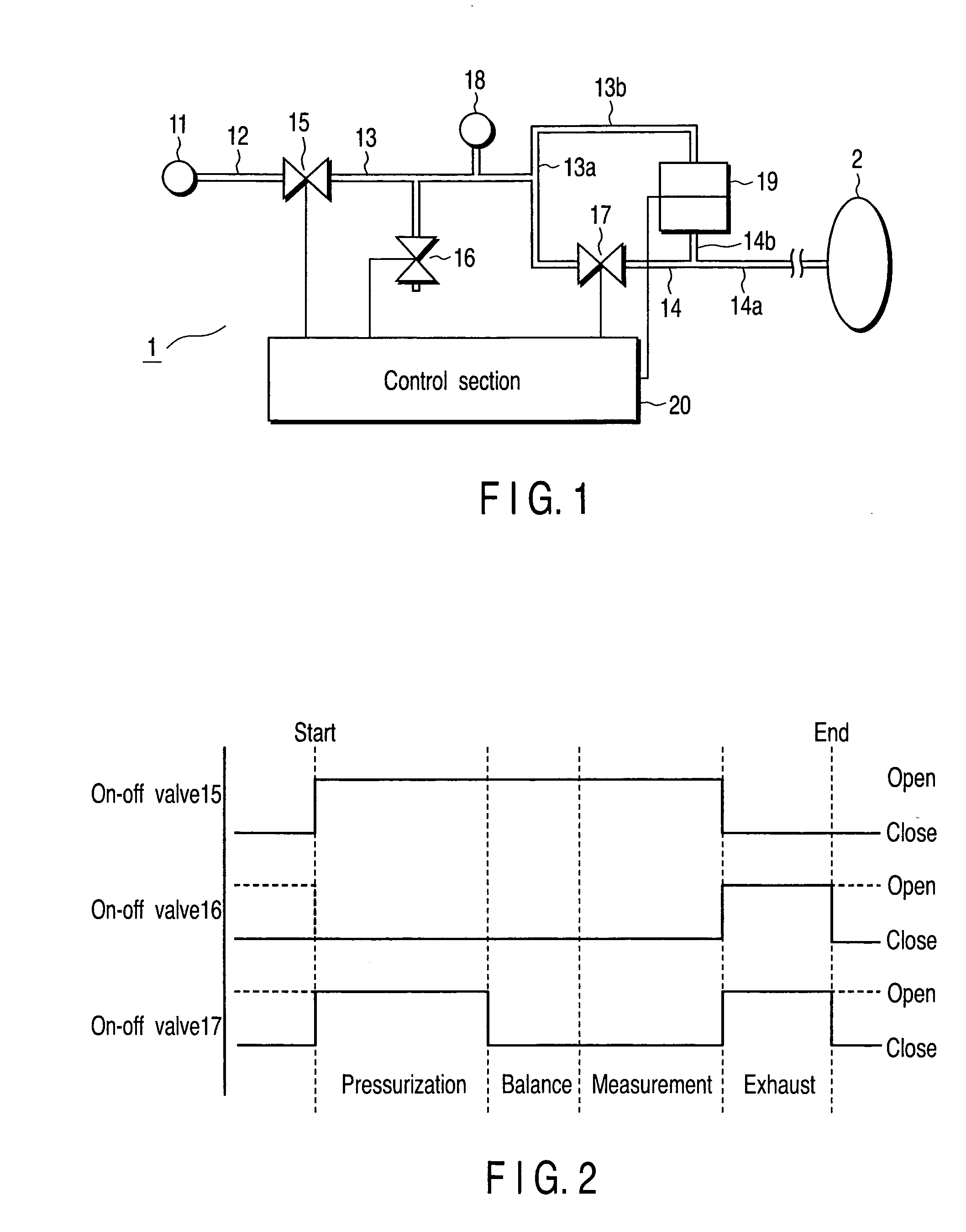
FIG. 1 is a block diagram showing the basic configuration of the leak tester according to the first embodiment. In FIG. 1, a leak tester 1 is composed of a pressurized gas source (a source to supply a pressurized gas) 11, pipes 12 and 13 (including 13a and 13b), a pipe 14 (including 14a and 14b), on-off valves 15, 16, and 17, a relief valve 18, a differential pressure sensor (differential pressure detecting section) 19, and a control section 20 operating as a pressure adjusting section. The pressurized gas source 11 is connected to the on-off valve 15 via the pipe 12. Moreover, the pipe 13 is connected to the on-off valve 15. The pipe 13 branches into two lines and one (pipe 13a) of the lines is connected to the on-off valve 17, while the other (pipe 13b) is connected to the differential pressure sens...

second embodiment

Now, a second embodiment of the present invention will be described. The second embodiment relates to a leak tester using a supplied-gas pump, for example, a diaphragm pump.

In the second embodiment, the supply of a pressurized gas is used as the supplied-gas pump. The second embodiment also comprises a mechanism that suppresses pulsation occurring in the supplied-gas pump.

FIG. 7 is a block diagram showing the basic configuration of the leak tester according to the second embodiment. In FIG. 7, the leak tester 3 is composed of a supplied-gas pump 41, on-off valves 42 and 43, a relief valve 44, a differential pressure sensor 45, a pulsation suppressing section 46, pipes 47, 48, and 49, and a control section 50. The description below will focus on parts different from the corresponding ones of the first embodiment. What corresponds to the on-off valve 15 according to the first embodiment is omitted. This is because a comparable operation can be achieved by turning on and off the su...


PUM


Abstract

A leak tester which detects leakage of a gas from a measured object, the leak tester including a source of a pressurized gas which supplies the pressurized gas, a differential pressure detecting section which detects a pressure difference between the pressure of a gas in the measured object and the pressure of a pressurized gas supplied by the source of the pressurized gas, and a pressure adjusting section which makes the pressure of the pressurized gas supplied by the source of the pressurized gas constant.

Description

BACKGROUND OF THE INVENTION 1. Field of the Invention The present invention relates to a leak tester that senses leakage from an airtight article, for example, an endoscope. 2. Description of the Related Art For example, an endoscope is a reusable medical apparatus and must thus be washed and disinfected. In this case, if a pin hole or a connection in the endoscope is loose, a liquid such as water or a disinfectant may enter the endoscope during washing or disinfection to cause a failure in an electric element such as an optical fiber or a CCD. Thus, to prevent such a failure, a leak test must be carried out on the endoscope. A common leak test method for an airtight article such as an endoscope comprises immersing the article into water, injecting pressurized air into the article, and checking for bubbles generated. However, this method requires a human operator to execute visual checks and thus fails to automate the leak test. As a result, a manual operation is constantly req...

Claims


Application Information

Patent Timeline
IPC IPC(8): A61B1/00G01M3/26G01M3/04G01M3/28G01M3/32
CPCG01M3/2815A61B1/00057G01M3/3263
Inventor GOCHO, MASANORI
Owner OLYMPUS CORP
Why Eureka
Try Eureka