Aircraft brake assembly

a technology for aircraft and brakes, applied in the direction of axially engaging brakes, actuators, and recording heads, etc., can solve the problems of not being able to avoid the removal of the torsion tube, and the disks cannot be removed in situ, so as to achieve the effect of minimal disassembly

Inactive Publication Date: 2005-03-17
MESSIER BUGATTI INC
View PDF11 Cites 14 Cited by
  • Summary
  • Abstract
  • Description
  • Claims
  • Application Information

AI Technical Summary

Benefits of technology

[0008] The present invention seeks to devise an aircraft brake assembly that does not present the above-specified drawbacks, and t

Problems solved by technology

It is therefore not possible under any circumstances for the disks to be removed in situ, it being necessary for that to be done in a workshop after the entire assembly constituted by

Method used


Image

  • Aircraft brake assembly
  • Aircraft brake assembly
  • Aircraft brake assembly

Examples


Embodiment Construction

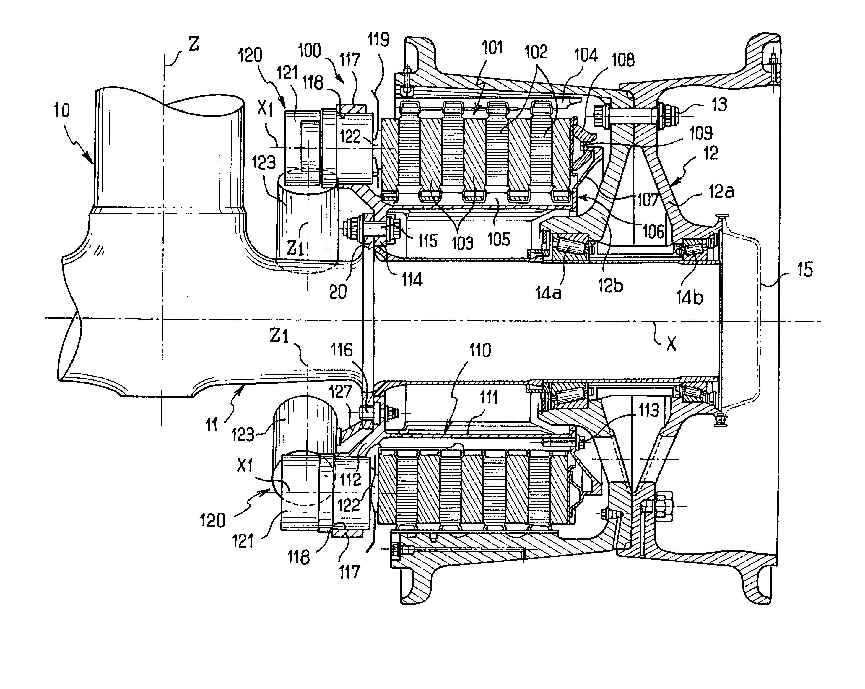
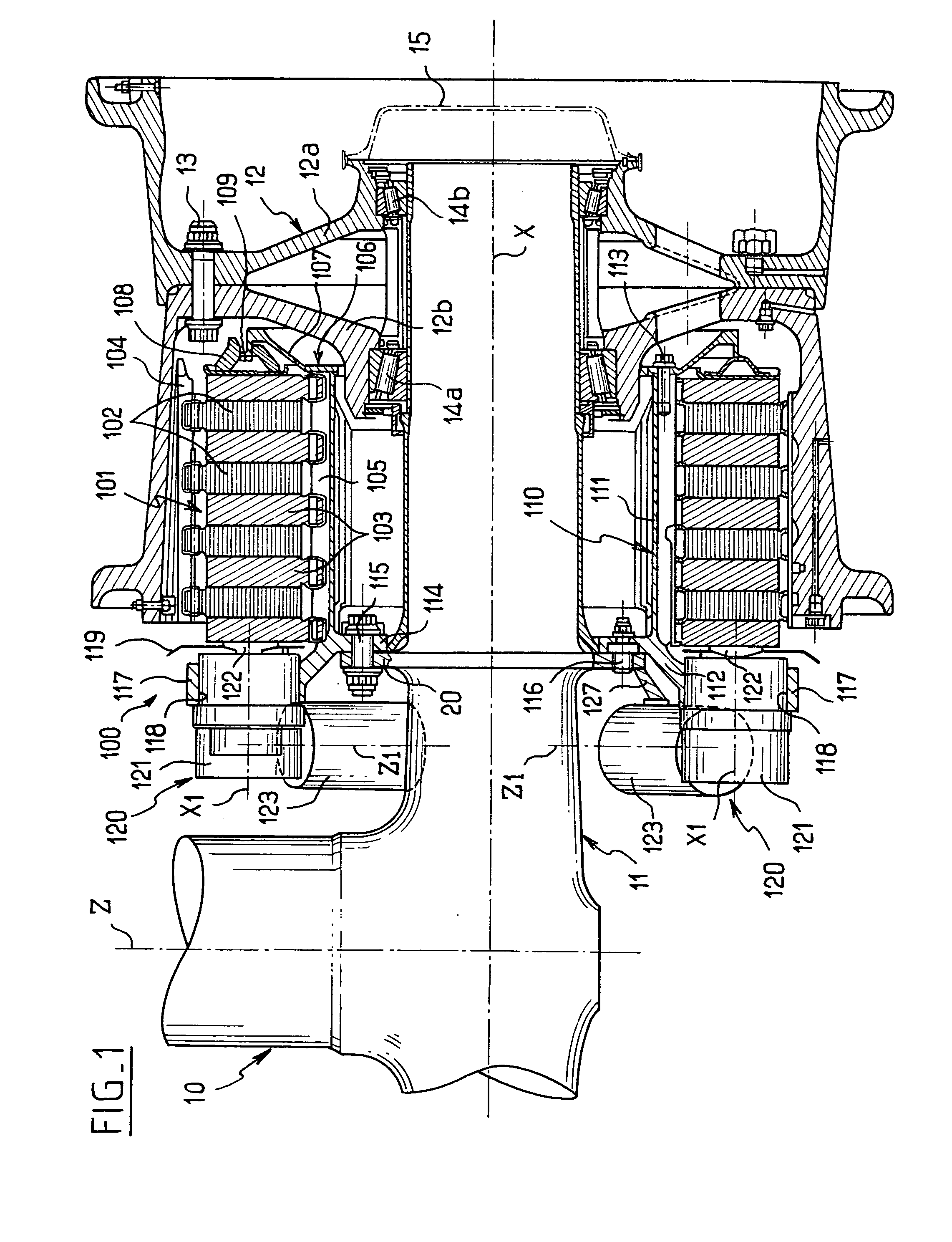
[0022]FIG. 1 shows a conventional landing gear structure with an essentially vertical rod 10 of axis Z terminated at its bottom end by two horizontal axles of axis X, only one of which is visible in the figure. The axle 11 carries a wheel 12, in this case implemented in the form of two components 12a, 12b, which are disposed side by side and which are secured to each other by bolt means 13. The wheel 12 rests via roller bearings 14a, 14b on the end of the axle 11. The hollow terminal portion of the axle 11 conventionally houses devices associated with generating a tachometer signal for measuring the speed of the wheel, which devices are not shown herein. All that is shown, in chain-dotted lines, is a closure cap 15 that is fixed on the wheel 12.

[0023] In order to brake the wheel 12, a brake assembly referenced 100 is provided. This brake assembly comprises a stack of disks 101 surrounding the wheel axle 11 coaxially.

[0024] The stack of disks 101 is made up of alternating rotor dis...


PUM


Abstract

The invention relates to an aircraft brake assembly comprising a stack of disks surrounding a wheel axle coaxially, said stack being made up of alternating rotor disks constrained in rotation with the wheel, and stator disks constrained in rotation with a torsion tube, and being pressed between a rear retaining piece and the pushers of a plurality of electro-mechanical actuators arranged circumferentially on front support ring. According to the invention, the torsion tube and the ring supporting the electro-mechanical actuators together constitute a one-piece unit which is fastened to the axle, and the rear retaining piece is fastened in separable manner on said one-piece unit at one end thereof.

Description

FIELD OF THE INVENTION [0001] The present invention relates to the field of braking airplanes, and more particularly to an aircraft brake assembly of the type comprising a stack of disks disposed coaxially around a wheel axle. BACKGROUND OF THE INVENTION [0002] Aircraft brake assemblies of conventional type comprise a stack of disks disposed coaxially around a wheel axle, said stack comprising alternating rotor disks constrained to rotate with the wheel, and stator disks constrained in rotation with a torsion tube. The stack of disks is pressed between a rear retaining piece and the pushers of a plurality of actuators disposed circumferentially around a front support ring, in accordance with the introductory portion of claim 1. [0003] In old designs that have been in use for many years, it has been the practice to use hydraulic actuators, where such actuators are fixed to a “hydraulic” ring having the various associated ducts mounted thereon. By way of example, reference can be made...

Claims


Application Information

Patent Timeline
IPC IPC(8): F16D55/00F16D55/36F16D65/14
CPCF16D55/36F16D2250/0084F16D2121/24F16D2055/0091
Inventor NARCY, JEANCHICO, PHILIPPE
Owner MESSIER BUGATTI INC
Why Eureka
Try Eureka