Apparatus for separating floating and non-floating particulate from a fluid stream

a technology of fluid stream and apparatus, which is applied in the direction of sedimentation settling tank, liquid displacement, separation process, etc., can solve the problems of increasing the likelihood of natural water contamination, increasing the strain on existing water transfer and treatment infrastructure, and increasing so as to maximize the ability to accumulate particulates, minimize the possibility of clogging, and maximize the effect of particulate removal

Active Publication Date: 2005-03-17
CONTECH ENGINEERED SOLUTIONS
View PDF74 Cites 59 Cited by
  • Summary
  • Abstract
  • Description
  • Claims
  • Application Information

AI Technical Summary

Benefits of technology

[0011] It is an object of the present invention to provide a separation system that is effective in accommodating varied fluid flow rates. It is also an object of the present invention to provide such a separation system that conforms or substantially conforms with established floating and non-floating particulate removal requirements. Further, it is an object of the

Problems solved by technology

If such diversion or treatment systems are not provided, particulate and contaminants located on or forming part of such structures may be carried by drain water or stormwater to the natural water bodies and contaminate them.
Land development produces increased levels of drain water and stormwater runoff, resulti

Method used


Image

  • Apparatus for separating floating and non-floating particulate from a fluid stream
  • Apparatus for separating floating and non-floating particulate from a fluid stream
  • Apparatus for separating floating and non-floating particulate from a fluid stream

Examples


Embodiment Construction

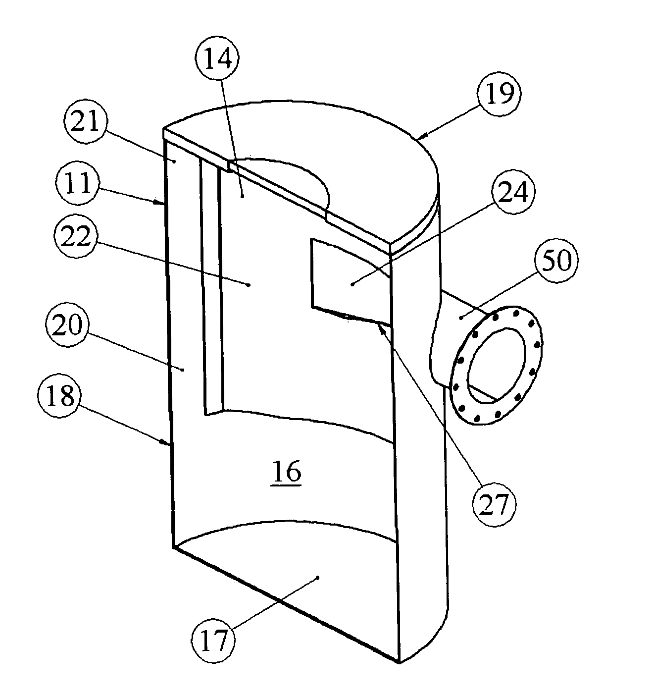
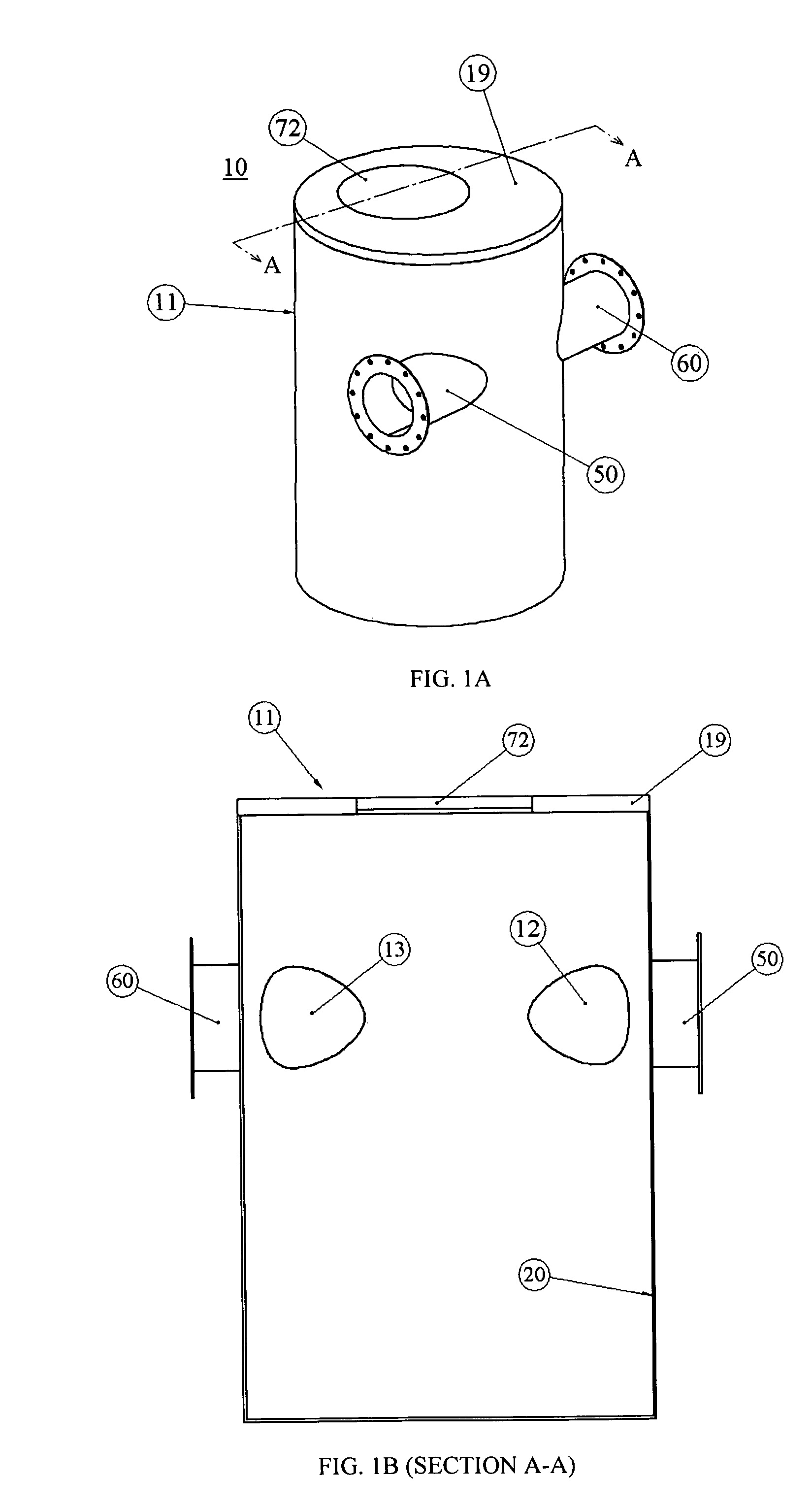
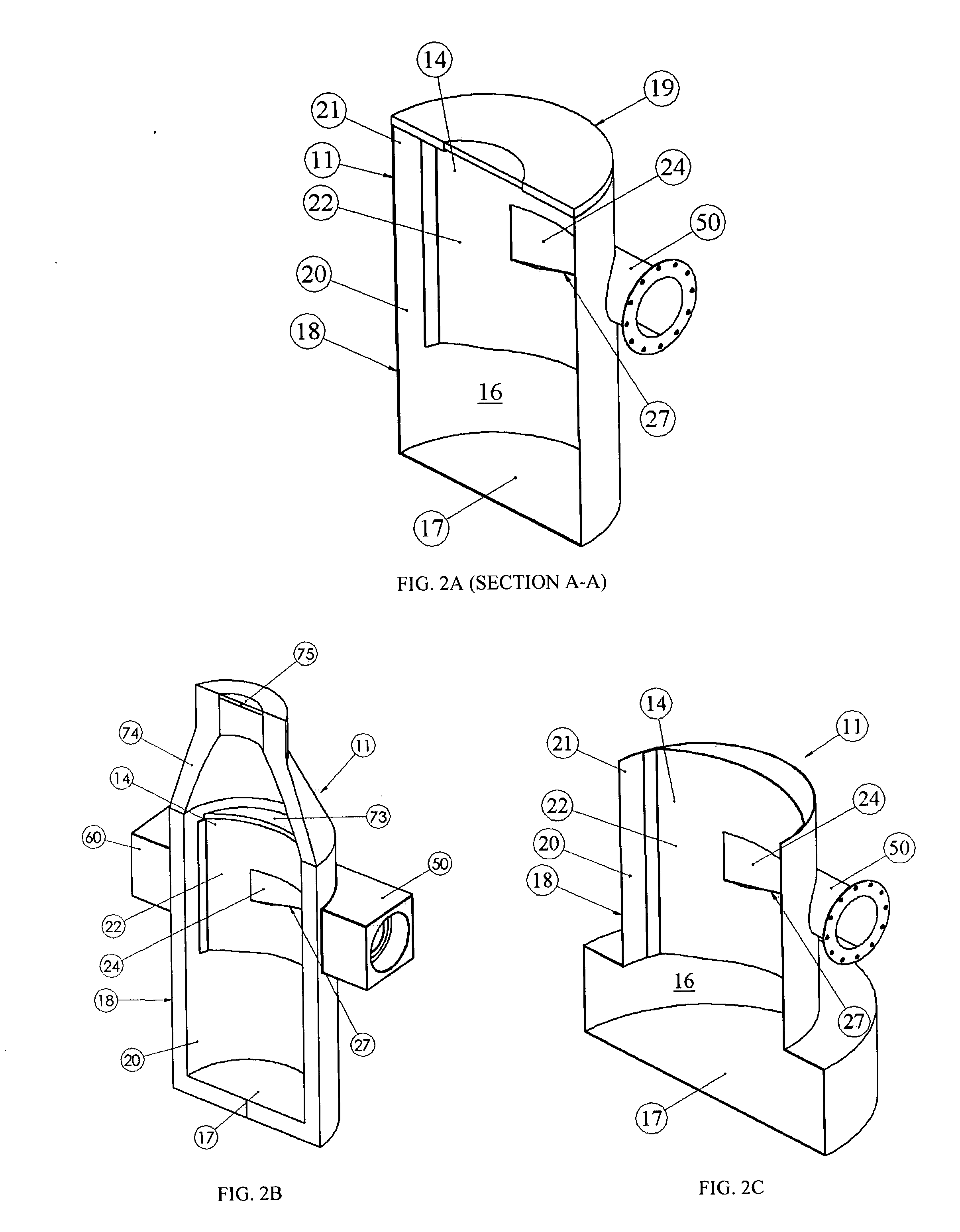
[0026] A separation system 10 of the present invention is illustrated in the accompanying drawings. As illustrated in FIGS. 1A and 1B, the system 10 includes a tank 11 having an inlet pipe stub 50 and an outlet pipe stub 60. The tank 11 is preferably made of concrete but may alternatively be fabricated in whole or in parts of metal, plastic, such as fiberglass, or other suitable materials. It may be fabricated of an existing manhole or manhole design and modified in the manner to be described herein. The inlet pipe stub 50 shown in FIG. 1A is represented as a short pipe terminating in a flange that may be used to connect the tank 11 to an upstream fluid transfer system. Similarly, the outlet pipe stub 60 shown in FIG. 1A is represented as a short pipe terminating in a flange that may be used to connect the tank to a downstream fluid transfer system. For example, the upstream fluid transfer system may include a drainage system from a roadway or a parking lot and the downstream fluid ...


PUM

PropertyMeasurementUnit
Flow rateaaaaaaaaaa
Shapeaaaaaaaaaa
Heightaaaaaaaaaa

Abstract

A fluid separation system includes a tank with a storage chamber for retaining floating and non-floating particulates. The tank includes a baffle for retaining floating particulates within the storage chamber and for directing flow out of the storage chamber. The tank also includes a bypass with an inlet flow control zone and an outlet flow control zone. The flow control zones are separated by a weir sized and positioned to regulate the fluid flow through a baffle port into the storage chamber. The weir also provides control of the flow rate at which incoming fluid is diverted directly through the bypass to the tank outlet rather than into the storage chamber. The baffle and/or the weir may be curved, and the baffle may include a complex curve, to aid in the smoothing of the fluid flow within the storage chamber to improve particulate separation.

Description

BACKGROUND OF THE INVENTION [0001] 1. Field of the Invention [0002] The present invention relates to systems for separating floating and non-floating particulate from fluids such as drain water and stormwater. More particularly, the present invention relates to a separation system that may be independent, or form part, of a larger fluid transfer system. [0003] 2. Description of the Prior Art [0004] Fluid transfer systems have been and will remain an important aspect of municipal services and commercial facilities management. The protection of ground water and natural bodies of water requires systems for diverting and / or treating water that contacts roadways, parking lots, and other man made structures. If such diversion or treatment systems are not provided, particulate and contaminants located on or forming part of such structures may be carried by drain water or stormwater to the natural water bodies and contaminate them. Local, state and federal laws and rules require municipalit...

Claims


Application Information

Patent Timeline
IPC IPC(8): B01D21/02
CPCB01D21/02B01D21/2411B01D21/2444B01D21/245B01D21/0006
Inventor ALLEN, VAIKKO P. IICOBB, DANIEL P.
Owner CONTECH ENGINEERED SOLUTIONS
Why Eureka
Try Eureka