
Drinking tube and cap assembly

a technology of drinking tube and cap, which is applied in the direction of caps, liquid handling, and closures using stoppers, can solve the problem of not providing a convenient path

Inactive Publication Date: 2005-03-17
CEZEAUX THOMAS EDWARD
View PDF48 Cites 47 Cited by
  • Summary
  • Abstract
  • Description
  • Claims
  • Application Information

AI Technical Summary

Benefits of technology

[0015] A water bottle type of hydration system is disclosed wherein the container is of a hard or rigid construction with an opening for filling the container. A removable cap closes the container. The cap includes a valve that provides an annular airflow path through the cap to provide an airflow path into the container when the contents of the bottle are being removed. An aperture is also provided through the middle of the valve, the aperture adapted to slidably and snugly accommodate an elongate flexible tube, such that one end of the tube extends into the container and the opposite end of the tube extends out of the container. The valve includes a tubular body portion that may be formed integral with the lid, and a valve stem that slidably engages the tubular body portion, the valve stem being movable between an open position wherein the annular airflow path is open, and a closed position wherein the annular airflow path is blocked. It will be appreciated that the valve, which may be a poppet-type valve, does not provide a convenient path for extracting liquid from the container as in prior art systems, but rather, the flexible tube provides a channel for extracting the liquid. The annular valve opens an airflow path to prevent the formation of a vacuum in the container that would inhibit the outflow of the liquid.

Problems solved by technology

It will be appreciated that the valve, which may be a poppet-type valve, does not provide a convenient path for extracting liquid from the container as in prior art systems, but rather, the flexible tube provides a channel for extracting the liquid.

Method used


Image

  • Drinking tube and cap assembly
  • Drinking tube and cap assembly
  • Drinking tube and cap assembly

Examples


Embodiment Construction

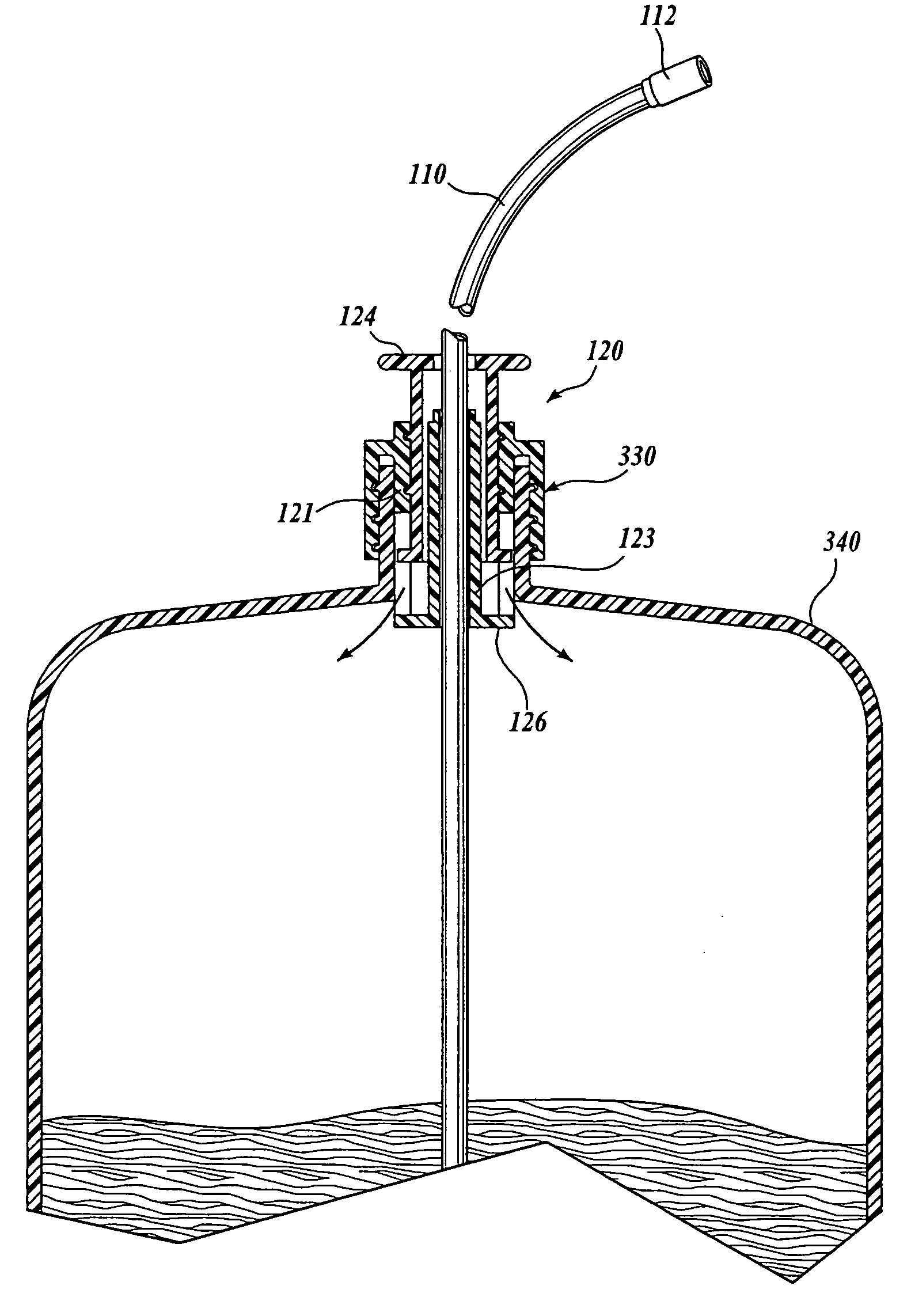
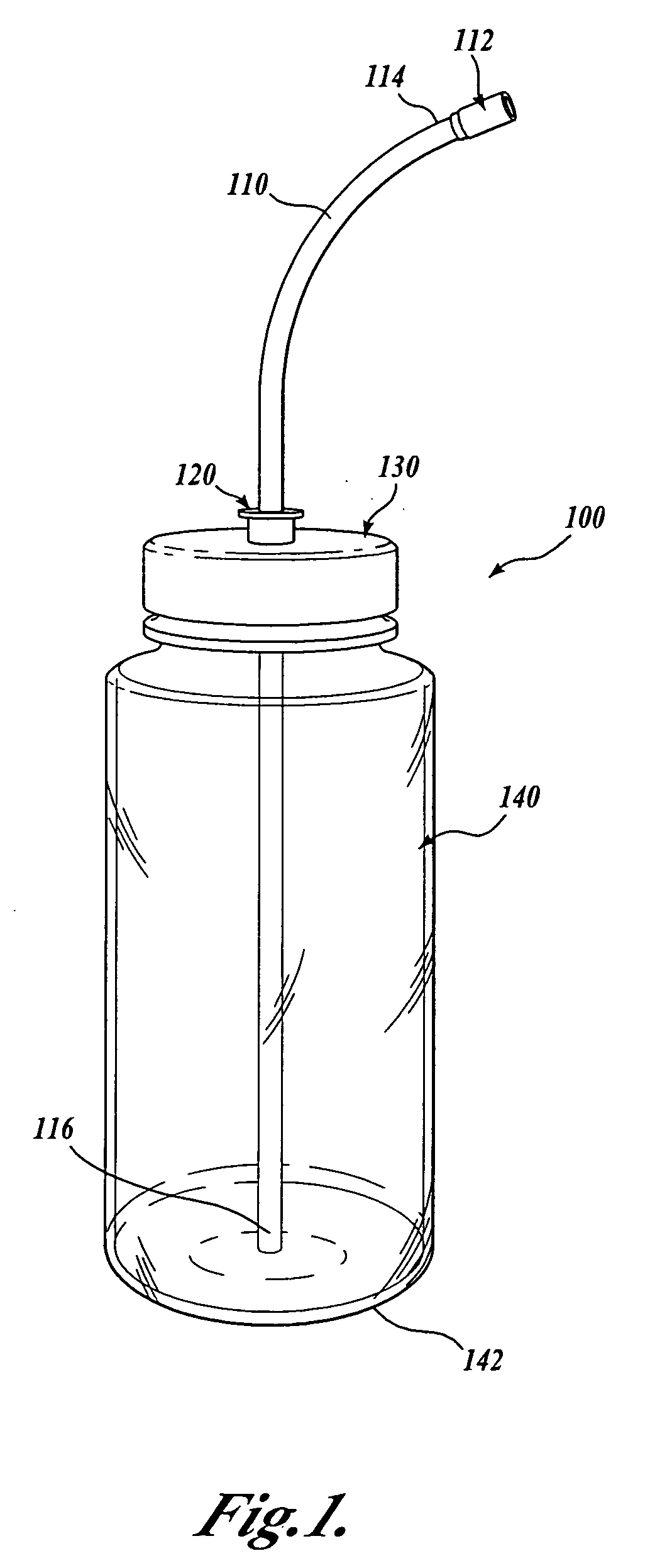
[0026] A currently preferred embodiment of the present invention will now be described with reference to the figures, wherein like numbers indicate like parts. Referring to FIG. 1, a hard container type of hydration assembly 100 is shown. The hydration assembly 100 includes a rigid or semirigid container 140 that may be made of any suitable material. In a preferred embodiment, the container 140 is formed from a hard polymer such as a polypropylene or polyethylene. Alternatively, the container may be formed from another suitably hard polymer, glass, aluminum, or other relatively rigid material. The container 140 is substantially cylindrical and may include contoured portions to facilitate holding the container 140 or mounting the container 140 to a holder. The container 140 is closable at the top with a removable cap 130. For example, the container 140 and cap 130 may have cooperative threaded portions (not shown) for securely attaching the cap 130 to the container 140. The container...


PUM


Abstract

A hydration system is disclosed for carrying readily dispensable fluids, such as water. A removable cap having an annular valve covers a container. A flexible tube is disposed through the center of the annular valve and extends generally to near the bottom of the container. A bite valve is attached to the end of the tube that is external to the container. When the annular valve is closed, the hydration system is substantially closed, preventing fluid loss. When the annular valve is opened, an air channel is created that allows air to enter the container, facilitating the flow of fluid from the container through the flexible tube. The annular valve may be a poppet-type valve having a valve stem that is movable between the closed position and the open position. The hydration system is sufficiently compact to be utilized with narrow-mouthed bottles.

Description

CROSS-REFERENCE TO RELATED APPLICATION [0001] This application claims the benefit of provisional Application No. 60 / 503,089, filed Sep. 15, 2003, the benefit of which is hereby claimed under 35 U.S.C. § 119.FIELD OF THE INVENTION [0002] The present invention relates to the field of hydration systems and, more particularly, to vented hydration systems having a hard container with a flexible drinking tube. BACKGROUND OF THE INVENTION [0003] Water bottles and similar hydration systems are popular, particularly among outdoor athletes—for example, by persons engaged in hiking, biking, skating, etc. Hydration systems are convenient for rehydrating a person who has lost body fluids as a result of heat, physical exertion, arid environment, and / or the passage of time. There are two general types of hydration systems—(1) hard or rigid / semirigid container systems, and (2) soft or flexible bladder systems. [0004] A hard container system includes a hard or semirigid container that is made from p...

Claims


Application Information

Patent Timeline
Patent Type & Authority Applications(United States)
IPC IPC(8): A45F3/16A47G19/22B65D47/32
CPCA45F3/16B65D47/32A47G19/2266
Inventor CEZEAUX, THOMAS EDWARD
Owner CEZEAUX THOMAS EDWARD
Features
  • Generate Ideas
  • Intellectual Property
  • Life Sciences
  • Materials
  • Tech Scout
  • Unparalleled Data Quality
  • Higher Quality Content
  • 60% Fewer Hallucinations
Learn More