Device for the transport of granular solid particles with a controlled flow rate

a flow rate and granular solid particle technology, applied in the direction of measurement devices, instruments, chemistry apparatuses and processes, etc., can solve the problems of not being essentially constant and uniform, device generally not completely satisfactory, and not being satisfactory

Active Publication Date: 2005-03-17
INST FR DU PETROLE
View PDF9 Cites 27 Cited by
  • Summary
  • Abstract
  • Description
  • Claims
  • Application Information

AI Technical Summary

Problems solved by technology

However, such a regulation is not satisfactory if a slight variation of the flow of secondary gas can generate a significant variation of the flow of catalyst.
Actually, this tends to promote fluctuations of flow, the former no longer being essentially constant and uniform.
Such a device generally is not completely satisfactory, for example, in an application to hydrocarbon catalytic reforming, because of the low flow rates of aeration gas that are used and because a slight variation of this flow rate can cause an abrupt variation of the catalyst flow rate.
Furthermore, the aeration gas, in this type of device, has the tendency to rise to a certain height of the vertical portion of the “L”-shaped pipe and participates only to a lesser extent in dilution and acceleration of particles to the pneumatic transport.
The “L” shape of the pipe, the injection point of the aeration gas, and the orientation of the injector of this device do not make it possible to obtain, a priori, good regulation of the flow of polymer particles during expansion for the same reasons already reported.

Method used


Image

  • Device for the transport of granular solid particles with a controlled flow rate
  • Device for the transport of granular solid particles with a controlled flow rate
  • Device for the transport of granular solid particles with a controlled flow rate

Examples


examples

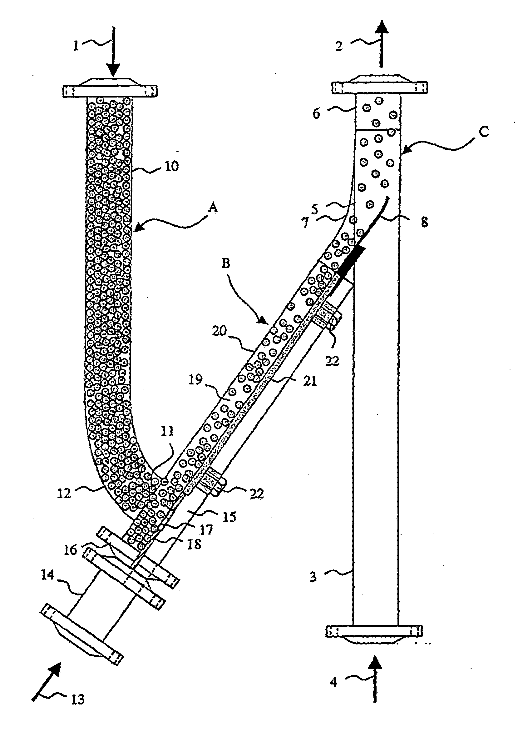
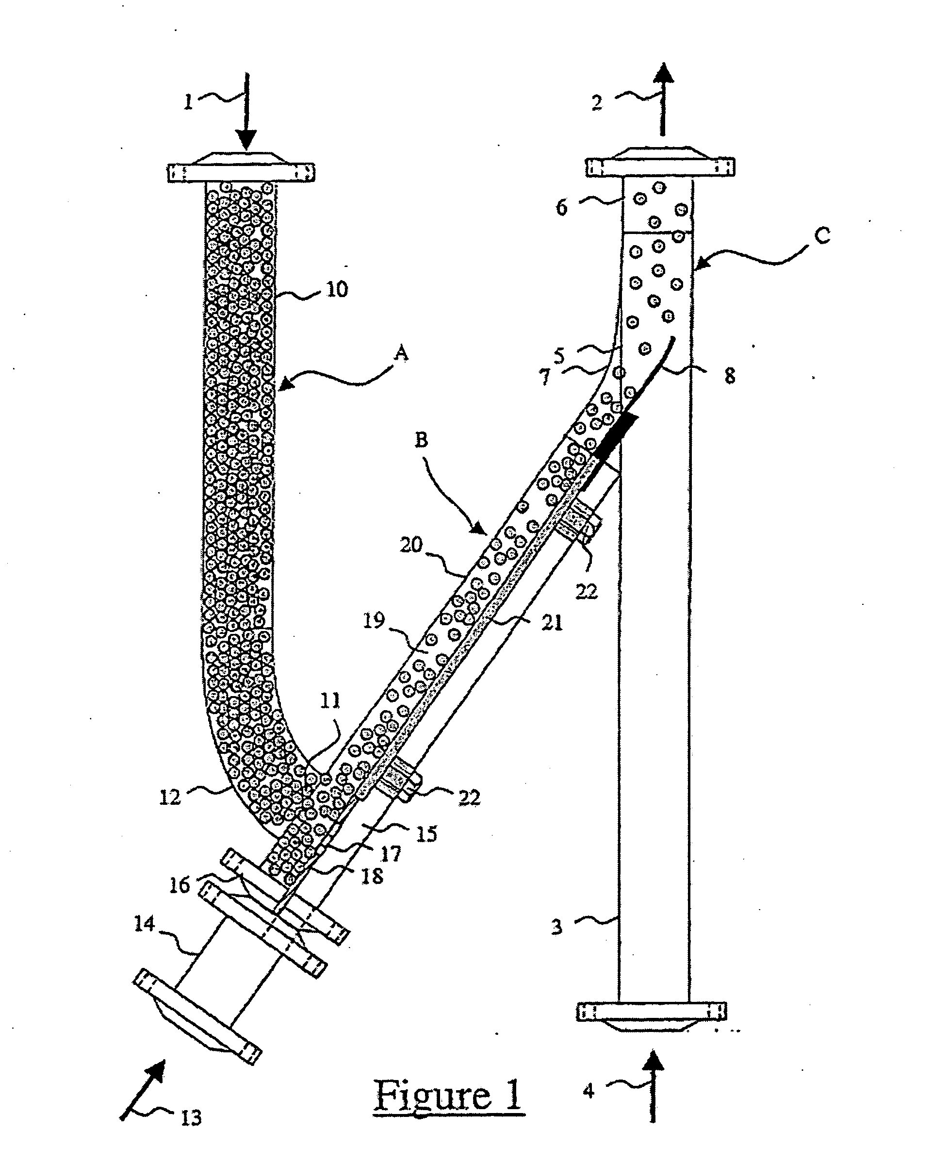
[0055] Two devices that exhibit different configurations were used on a test-bed so as to measure the evolution of the flow rate of solid particles based on the flow rate of secondary gas and to determine the best embodiment for the regulation of the flow rate of solid particles.

[0056] The two devices A1 and A2 are produced on the basis of the embodiment exhibited in FIG. 1, with differences for A2, explained below, whereby these differences are linked to the position of the secondary-gas injection means and the flow direction of this gas.

[0057] Device A1 is exactly as shown in FIG. 1. A1 thus exhibits a transfer pipe (very inclined) whose angle relative to the upward vertical is 30 degrees, and secondary-gas injection means that comprise orifices mounted on the base of the flow zone in the dense phase opposite the opening of the feed portion. The secondary gas injection is therefore done in a direction that is essentially in counter-current relative to the flow direction of the p...


PUM


Abstract

Process and device for the transport of granular solids with a controlled flow rate, in particular for the transport of catalyst in a hydrocarbon reforming unit. The device comprises a gravity-feed pipe (A) for solid particles in the dense phase, a pneumatic transport pipe (C) in the dilute phase, and an inclined transfer pipe (B) that connects, without a buffer space, the base of the feed pipe to the pneumatic transport pipe, whereby this transfer pipe comprises means (17, 18, 35) for injection of a secondary gas located at the junction between the feed pipe and the transfer pipe.

Description

[0001] This invention relates to the pneumatic transports of granular solid particles and the installations that implement this type of transport in various fields of the industry, in particular in chemistry and in the petroleum industry. [0002] The invention indicates in particular the field of the devices and installations that are used in the units for catalytic reforming of hydrocarbons for the production of aromatic gasoline making it possible to transport the catalyst from one chamber to another. PRIOR ART [0003] The techniques for transport of granular particles (particles of a dimension that is close to 1 or several mm) are specific. They are different in particular from techniques for transport of easily fluidizable fine particles, such as catalyst particles of fluid catalytic cracking, whose mean dimension is close to 100 micrometers. The granular particles actually have flow properties that are very different from those of easily fluidizable fine particles. [0004] In the ...

Claims


Application Information

Patent Timeline
Patent Type & Authority Applications(United States)
IPC IPC(8): B01J8/00B65G53/10B65G53/14B65G53/16B65G53/18B65G53/20B65G53/40B65G53/42B65G53/50B65G53/66
CPCB01J8/0025B01J2208/00752B65G53/10B65G53/14B65G53/50B65G53/18B65G53/20B65G53/42B65G53/16
Inventor GILLE, DAMIENFONT, PATRICE
Owner INST FR DU PETROLE
Why Eureka
Try Eureka