Method and system for predicting lateral acceleration of a vehicle

a technology of lateral acceleration and vehicle, applied in the direction of brake systems, process and machine control, instruments, etc., can solve the problems of rsc function only having limited time to slow the vehicle's speed, and the lateral acceleration sufficient to create a vehicle rollover danger can develop very quickly

Inactive Publication Date: 2005-03-17
WABCO GMBH
View PDF14 Cites 42 Cited by
  • Summary
  • Abstract
  • Description
  • Claims
  • Application Information

AI Technical Summary

Benefits of technology

[0016] The present invention accordingly comprises the various steps and the relation of one or more of such steps with respect to each of the others, and embodies features of construction, combina...

Problems solved by technology

At high driving speed and during dynamic steering movement by the driver, lateral acceleration sufficient to create a vehicle rollover danger can deve...

Method used


Image

  • Method and system for predicting lateral acceleration of a vehicle
  • Method and system for predicting lateral acceleration of a vehicle
  • Method and system for predicting lateral acceleration of a vehicle

Examples


Embodiment Construction

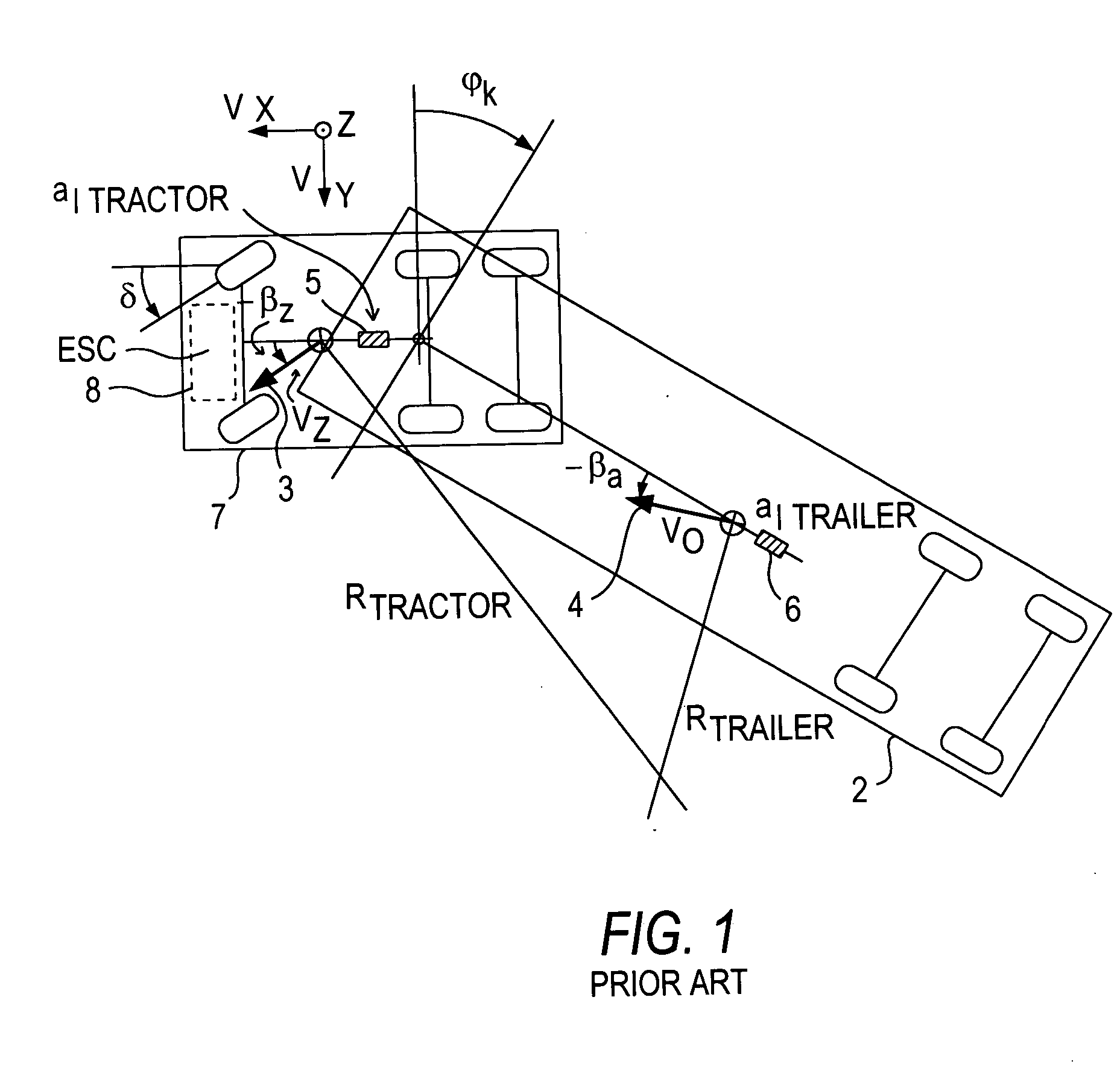
[0020] Referring now to the drawing figures, FIG. 1 is an overhead view of an articulated train negotiating a left-hand curve. The vehicle tractor is denoted by reference number 1, and the semitrailer by reference number 2. The center of gravity of tractor 1 is moving with a speed vz in the direction of arrow 3. The center of gravity of semitrailer 2 is moving with a speed va in the direction of arrow 4.

[0021] Arrows 3, 4 extend from the center of gravity of the tractor 1 and semitrailer 2, respectively, and do not coincide with the longitudinal axes of the two vehicle train parts. It follows from this alignment that the vehicle as illustrated is negotiating a curve.

[0022] The side-slip angle of tractor 1, or in other words the deviation of its actual direction of movement from its longitudinal axis, is −βz. The corresponding slide-slip angle of the semitrailer is −βa. Here, the minus signs indicate that the vehicle is negotiating a left-hand curve.

[0023] The steering angle of th...


PUM


Abstract

The present invention provides a method and system for predicting the lateral acceleration of a vehicle, especially a commercial vehicle train. The expected lateral acceleration is used to prevent vehicle rollover during critical driving situations. The expected lateral acceleration is calculated in advance using the vehicle's steering angle and speed, or obtained from a lookup table containing predefined combinations of steering angles and speeds corresponding to lateral acceleration values. The expected lateral acceleration is used in the place of, or in addition to, measured instantaneous lateral acceleration to realize a lead time in which early braking of the vehicle by an electronic stability control system or a rollover stability control system is effected, compared to regulation based on measured lateral acceleration alone.

Description

BACKGROUND OF THE INVENTION [0001] The present invention is generally directed to a method and system for predicting the lateral acceleration of a vehicle. [0002] Modern road vehicles, including commercial vehicles in particular, are increasingly equipped with electronic brake systems (EBSs). In such vehicles, signal transmission from the brake pedal to the EBS electronics takes place via an electric connecting line. Admission of fluid to the brake cylinders takes place via solenoid valves connected upstream. In this way the brake pressure can be increased, held steady or decreased. The solenoid valves are actuated electrically by the EBS electronics. [0003] In contrast to a conventional mechanical brake system, the brakes of a vehicle equipped with an EBS can be acted on by brake fluid, and thus the vehicle can be braked independently of the driver. This capability is exploited by various systems which can be integrated into the EBS. Examples of such systems include distance contro...

Claims


Application Information

Patent Timeline
IPC IPC(8): B60G17/015B60G17/016B60G21/10B60K31/00B60R16/02B60T8/172B60T8/1755B60T8/1764B60T8/24B60T8/58B60T8/60B62D37/00G01P9/00G06F17/00
CPCB60G17/0162B60G2300/042B60G2400/104B60G2800/702Y02T10/84B60T8/172B60T8/17554B60T2230/03B60T2230/06B60G2800/9124
Inventor HEUER, BERNDFRANKE, TORSTEN
Owner WABCO GMBH
Why Eureka
Try Eureka