Hold down clip

a clip and clamping technology, applied in the direction of snap fasteners, buckles, machine supports, etc., can solve the problems of affecting the installation effect, so as to achieve the effect of easy removal and application

Active Publication Date: 2005-03-24
WORTHINGTON ARMSTRONG VENTURE
View PDF34 Cites 12 Cited by
  • Summary
  • Abstract
  • Description
  • Claims
  • Application Information

AI Technical Summary

Benefits of technology

[0015] The upper inverted U shaped section of a relatively rigid plastic is resilient enough to spread and snap over various size bulbs of a grid beam, while the more flexible PVC of the hinge portions acts to bias the legs of the more rigid plastic, downward, giving a spring effect.
[0016] The clip works with virtually any thickness panel, since the legs can flex over the varying thicknesses of the panel. The clip can be easily applied and removed.

Problems solved by technology

For instance, in suspended ceilings in gymnasiums and and other large open areas, the ceiling is subjected to gusts of air or wind that may blow the panels out of place if retaining members are not used.
These prior cut clips vary in complexity, effectiveness, and ease of installation.

Method used


Image

  • Hold down clip
  • Hold down clip
  • Hold down clip

Examples


Embodiment Construction

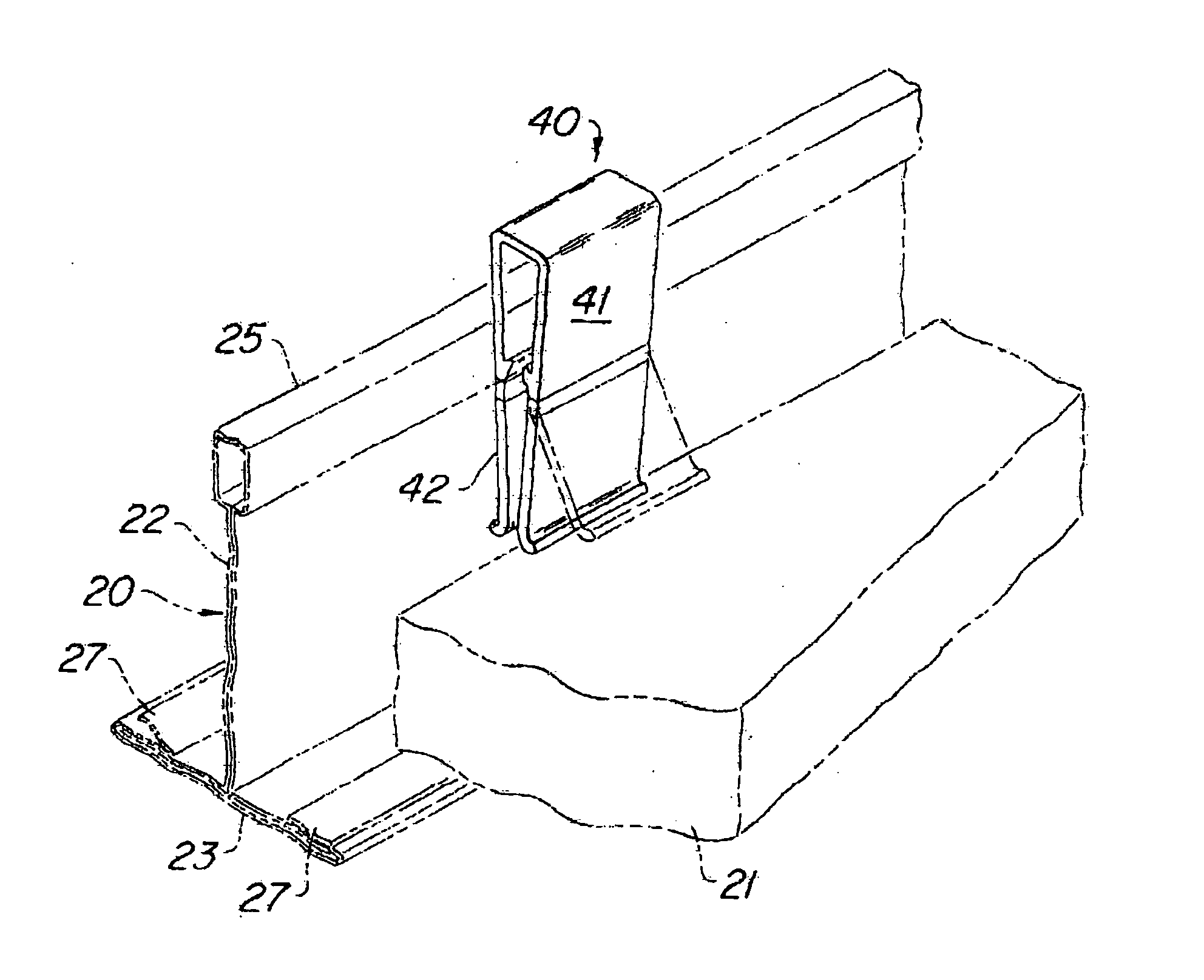
[0025] As seen particularly in FIG. 1, a grid beam 20 of the type shown in above referred to copending U.S. patent application Ser. No. 10 / 346,039 forms part of a grid that receives panels 21 to form a suspended ceiling. The grid is supported from a structural ceiling by wires. Such a ceiling is shown, for instance, in U.S. Pat. No. 4,827,681, referred to above, and is extensively used in building construction.

[0026] The beam 20 itself is of an inverted T shape with essentially a vertical web 22 and a horizontal flange 23. The web 22 has at the top some form of bulb 25, which provides a stiffener to the web 22. At the bottom of web 22, the flange 23 extends on each side of the web 22, to provide a support for a panel 21 which rest in a rectangular grid opening created by interlocking grid beams. Such construction is well known.

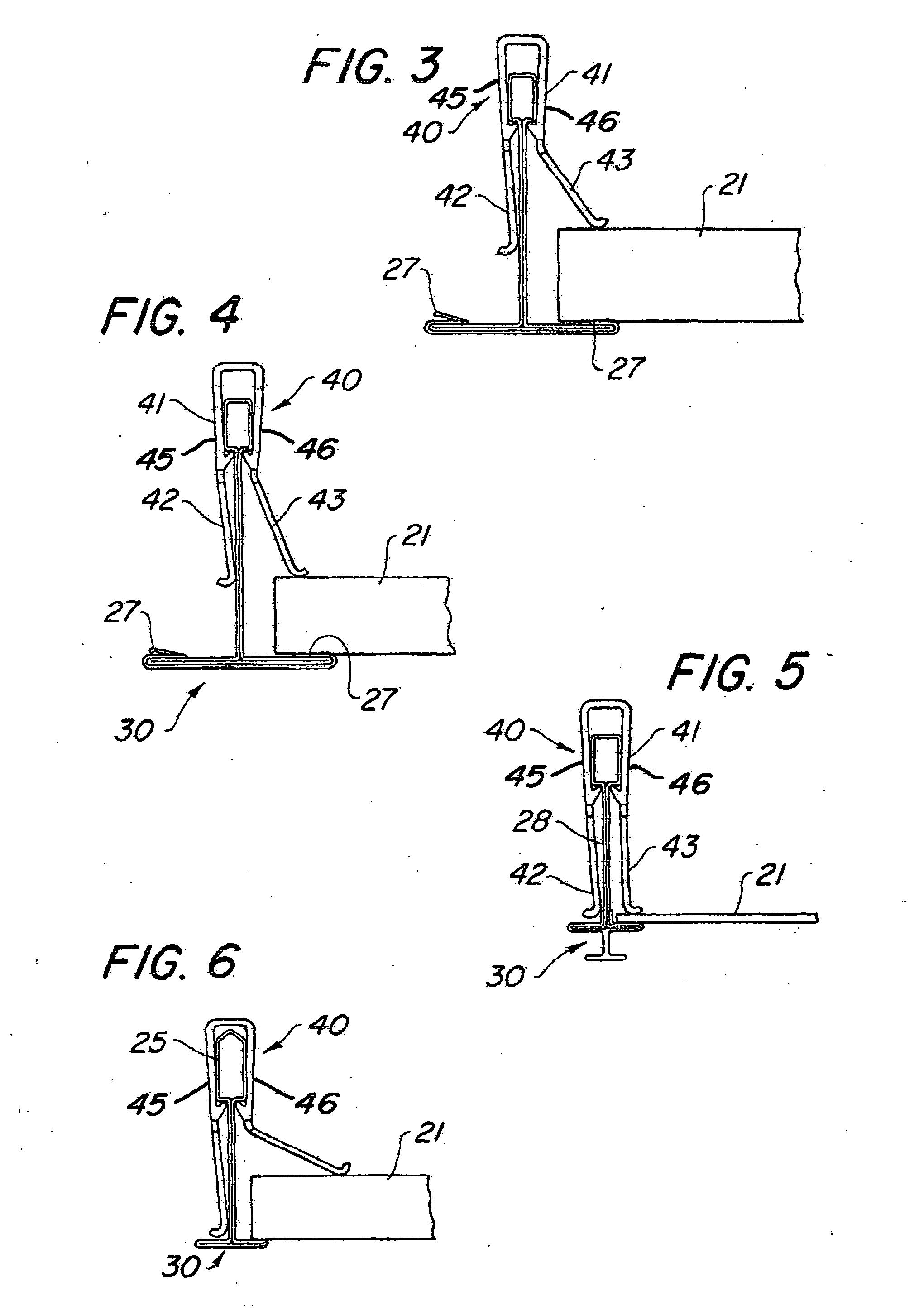
[0027] In the grid beam depicted in FIGS. 1, 3, and 4, plastic flaps 27, biased upward, yield to provide seals between the panel 21 and the flange 23. Such ...


PUM


Abstract

A clip to hold panels in place in grid openings in a suspended ceiling. The clip is integrally formed and includes relatively flexible hinges that bias relatively rigid sections against the panels.

Description

BACKGROUND OF THE INVENTION [0001] 1. Field of the Invention [0002] The invention relates to a suspended grid ceiling having panels in grid openings, and particularly to such ceilings where there is a special need to hold the panels down in place on the flanges of the beams forming the grid openings. [0003] 2. The Prior Art [0004] Suspended ceilings used extensively in building construction have a grid of intersecting beams suspended by wires from a structural ceiling. The grid has rectangular openings formed by the intersecting beams, that receive laid in panels. Such a ceiling is shown in U.S. Pat. No. 4,827,681, for instance, incorporated herein by reference. [0005] The beams are formed of a web of flat steel roll formed into an inverted T. The panels are supported on the flanges of the T, with the hanging wires anchored above in the structural ceiling, and connected below to holes in the web of the beam. [0006] Generally, in suspended ceilings, the weight of a panel is enough to...

Claims


Application Information

Patent Timeline
Patent Type & Authority Applications(United States)
IPC IPC(8): E04B9/26
CPCE04B9/242Y10T24/44393Y10T24/44769Y10T24/44786
Inventor AURIEMMA, JOSEPH
Owner WORTHINGTON ARMSTRONG VENTURE
Why Eureka
Try Eureka