Method for restricting excessive temperature rise of filter in internal combustion engine

a technology of internal combustion engine and filter, which is applied in the direction of machines/engines, electrical control, separation processes, etc., can solve the problems of reducing affecting the efficiency of the filter, so as to reduce reduce the effect of reducing the risk of affecting the operation of the filter, and reduce the effect of reducing the risk of affecting the operation

Active Publication Date: 2005-03-24
TOYOTA JIDOSHA KK
View PDF7 Cites 30 Cited by
  • Summary
  • Abstract
  • Description
  • Claims
  • Application Information

AI Technical Summary

Benefits of technology

[0029] By such correction, the oxygen concentration in the inflowing exhaust gas can be adjusted to the target oxygen concentration more accurately as with the above process. Thus, the temperature of the filter can be controlled with improved accuracy, and therefore it is possible to restrict an excessive temperature rise of the filter more reliably.
[0030] In the present invention, the establishment of the condition with which it is anticipated that the temperature of the filter will become equal to or higher than the specified tempe

Problems solved by technology

In the filter regeneration process, there is a risk that the temperature of the filter can be raised excessively by the heat generated by oxidation of the particulate matter, so that heat deterioration of the filter can be accelerated or the filter can be melted.
In that case, while the oxygen concentration in the exhaust gas is made low, removal of the particulate matter from the fi

Method used


Image

  • Method for restricting excessive temperature rise of filter in internal combustion engine
  • Method for restricting excessive temperature rise of filter in internal combustion engine
  • Method for restricting excessive temperature rise of filter in internal combustion engine

Examples


Embodiment Construction

[0040] In the following, an embodiment in which the method of restricting an excessive temperature rise of a filter in an internal combustion engine according to the present invention is applied will be described with reference to accompanying drawings.

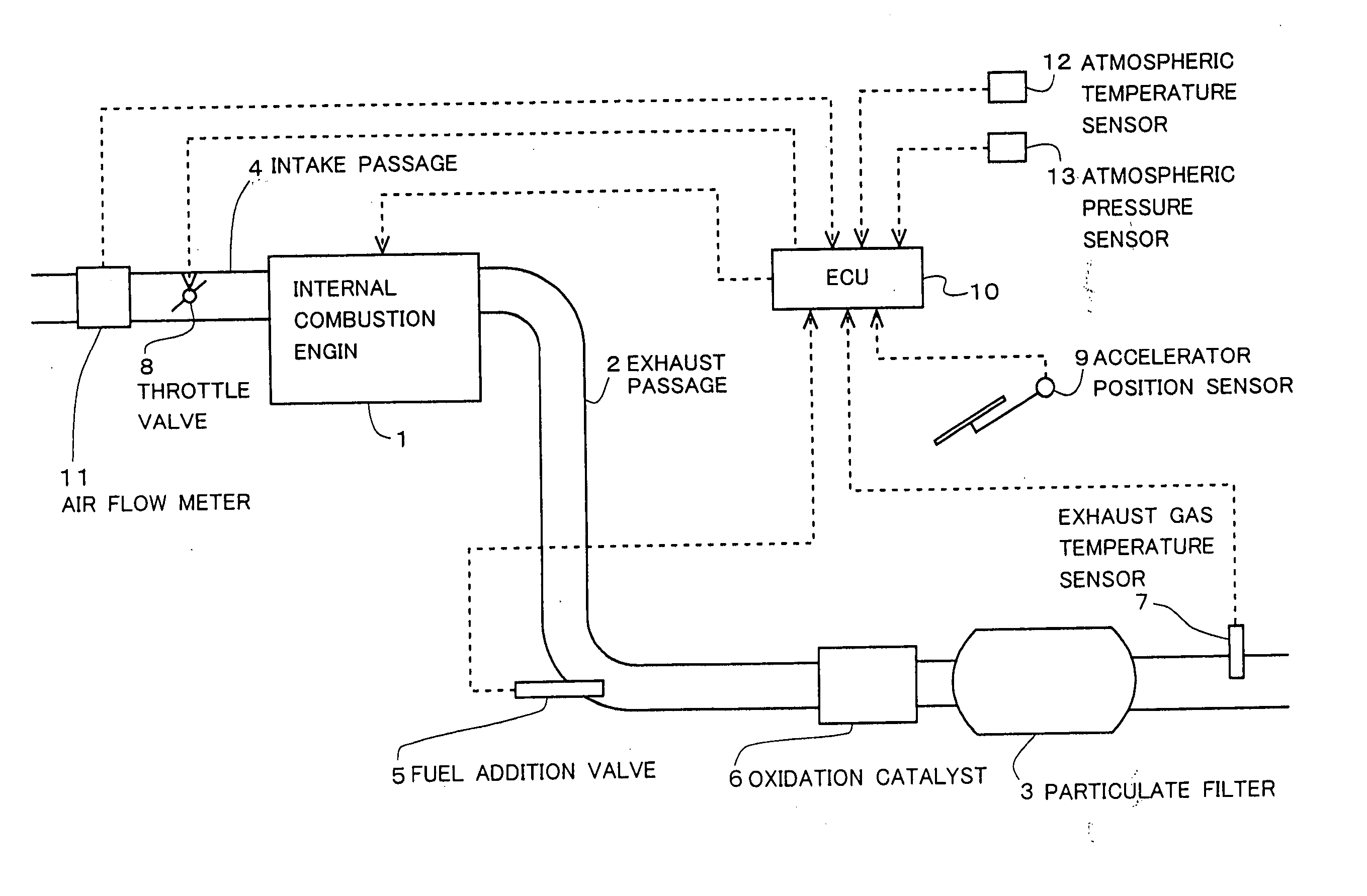
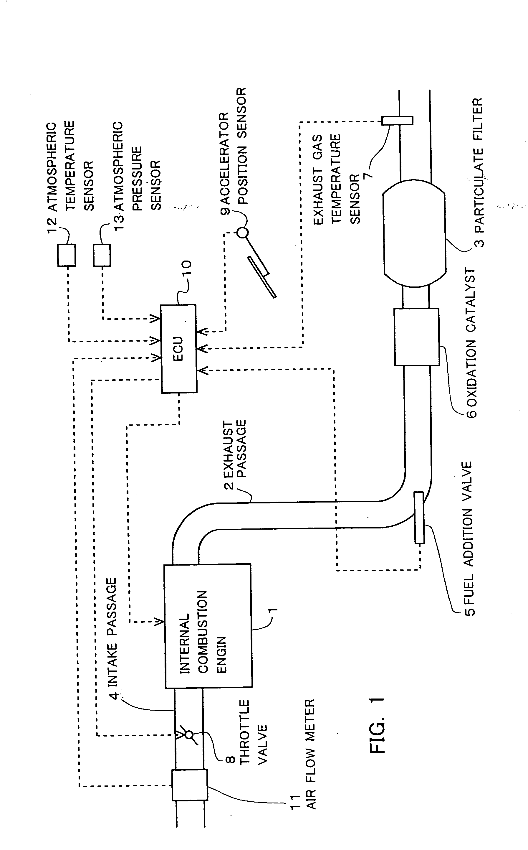
[0041] Here, the description will be directed to the case in which the present invention is applied to a diesel engine for driving vehicles. FIG. 1 is a view showing the schematic construction of an internal combustion engine, its intake, exhaust systems and its control system according to this embodiment.

[0042] The internal combustion engine 1 is a diesel engine for driving vehicles. The internal combustion engine 1 is connected with an intake passage 4 and an exhaust passage 2. In the intake passage 4, an air flow meter 11 and a throttle valve 8 are provided. On the other hand, in the exhaust passage 2, a particulate filter 3 (which will be simply referred to as the filter 3, hereinafter) for collecting particulate matter such as ...


PUM

PropertyMeasurementUnit
Temperatureaaaaaaaaaa
Pressureaaaaaaaaaa
Concentrationaaaaaaaaaa

Abstract

A method for restricting an excessive temperature rise in an internal combustion engine according to the present invention can provide a technology that enable to restrict an excessive temperature rise of a filter more reliably in an internal combustion engine having the filter provided in the exhaust passage for collecting particulate matter in the exhaust gas. In that method, when the running state of the internal combustion engine becomes idle running during the filter regeneration process, the oxygen concentration in the exhaust gas flowing into the filter is reduced. After that, when the running state of the internal combustion engine shifts from the idle running to a running state with an engine load higher than in the idle running, the oxygen concentration in the exhaust gas flowing into the filter is gradually increased.

Description

BACKGROUND OF THE INVENTION [0001] 1. Field of the Invention [0002] The present invention relates to a filter excessive temperature rise restricting method for restricting an excessive temperature rise of a filter in an internal combustion engine equipped with the filter for collecting particulate matter contained in the exhaust gas provided in the exhaust passage. [0003] 2. Description of the Related Art [0004] Internal combustion engines having a filter provided in the exhaust passage to collect particulate matter such as soot contained in the exhaust gas are known. In the internal combustion engine having a filter, a filter regeneration process is performed when the amount of the particulate matter depositing on the filter becomes equal to or larger than a specified amount. In the filter regeneration process, the temperature of the filter is raised to oxidize and remove the particulate matter depositing on the filter. [0005] In the filter regeneration process, there is a risk tha...

Claims


Application Information

Patent Timeline
IPC IPC(8): B01D46/42F02D43/00F01N3/02F01N3/023F01N3/025F01N3/029F01N3/035F01N3/08F01N3/24F01N13/02F02D41/02F02D41/08F02D41/22F02D41/38F02D41/40F02D45/00
CPCF01N3/0253F01N3/035F01N3/0821F01N3/0842F02D41/029F01N13/009F02D41/187F02D41/405F02D2200/0414F02D2200/602F02D2200/703F02D41/1446
Inventor KOGO, TOMOYUKIHASHIZUME, TAKESHI
Owner TOYOTA JIDOSHA KK
Why Eureka
Try Eureka