Blowoff valve assembly with integrated pressure switch

Inactive Publication Date: 2005-03-24
DELPHI TECH INC
View PDF13 Cites 15 Cited by
  • Summary
  • Abstract
  • Description
  • Claims
  • Application Information

AI Technical Summary

Problems solved by technology

However, if the pressure of the refrigerant increase further to a predetermined upper th

Method used


Image

  • Blowoff valve assembly with integrated pressure switch
  • Blowoff valve assembly with integrated pressure switch
  • Blowoff valve assembly with integrated pressure switch

Examples


Embodiment Construction

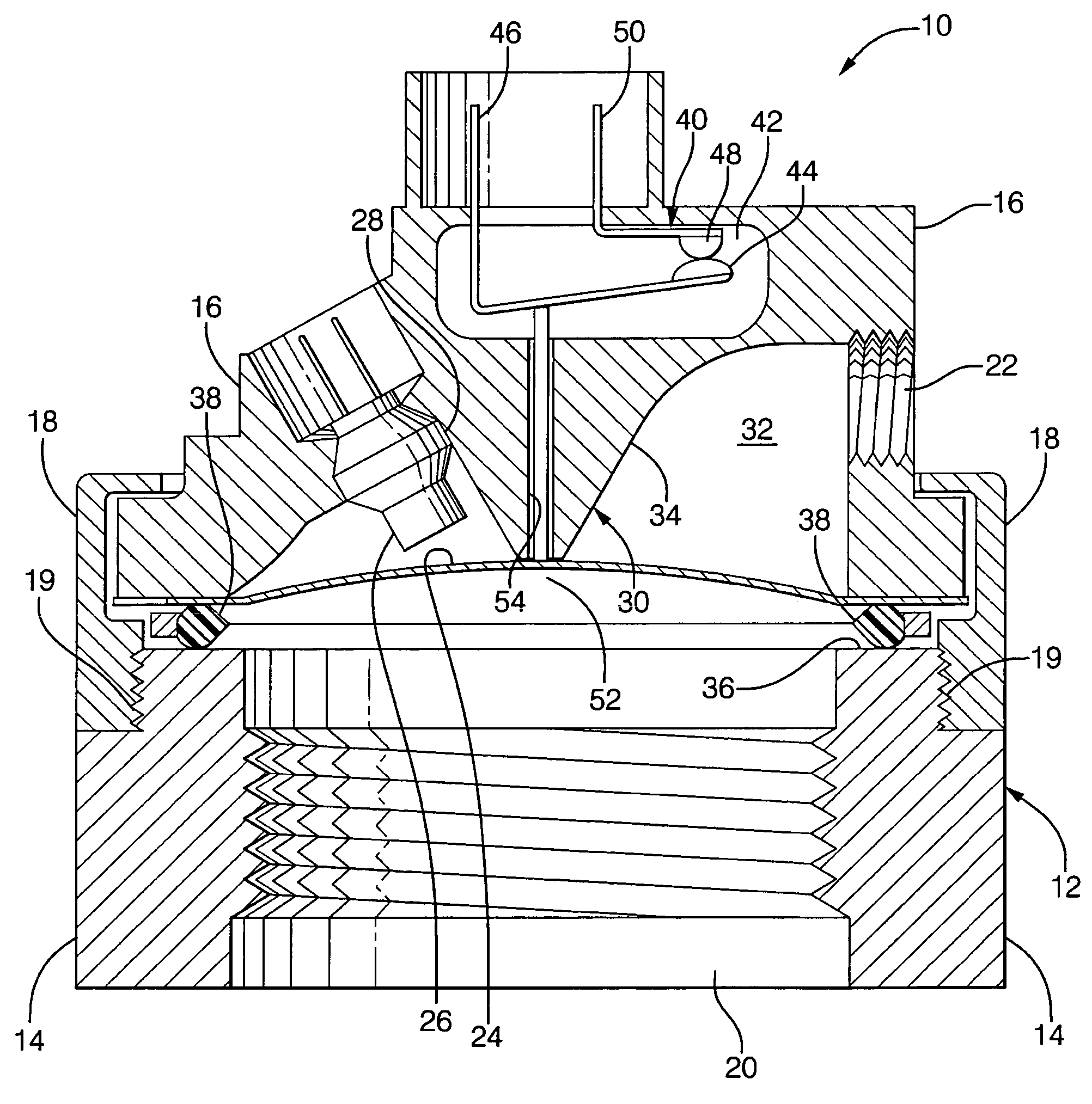
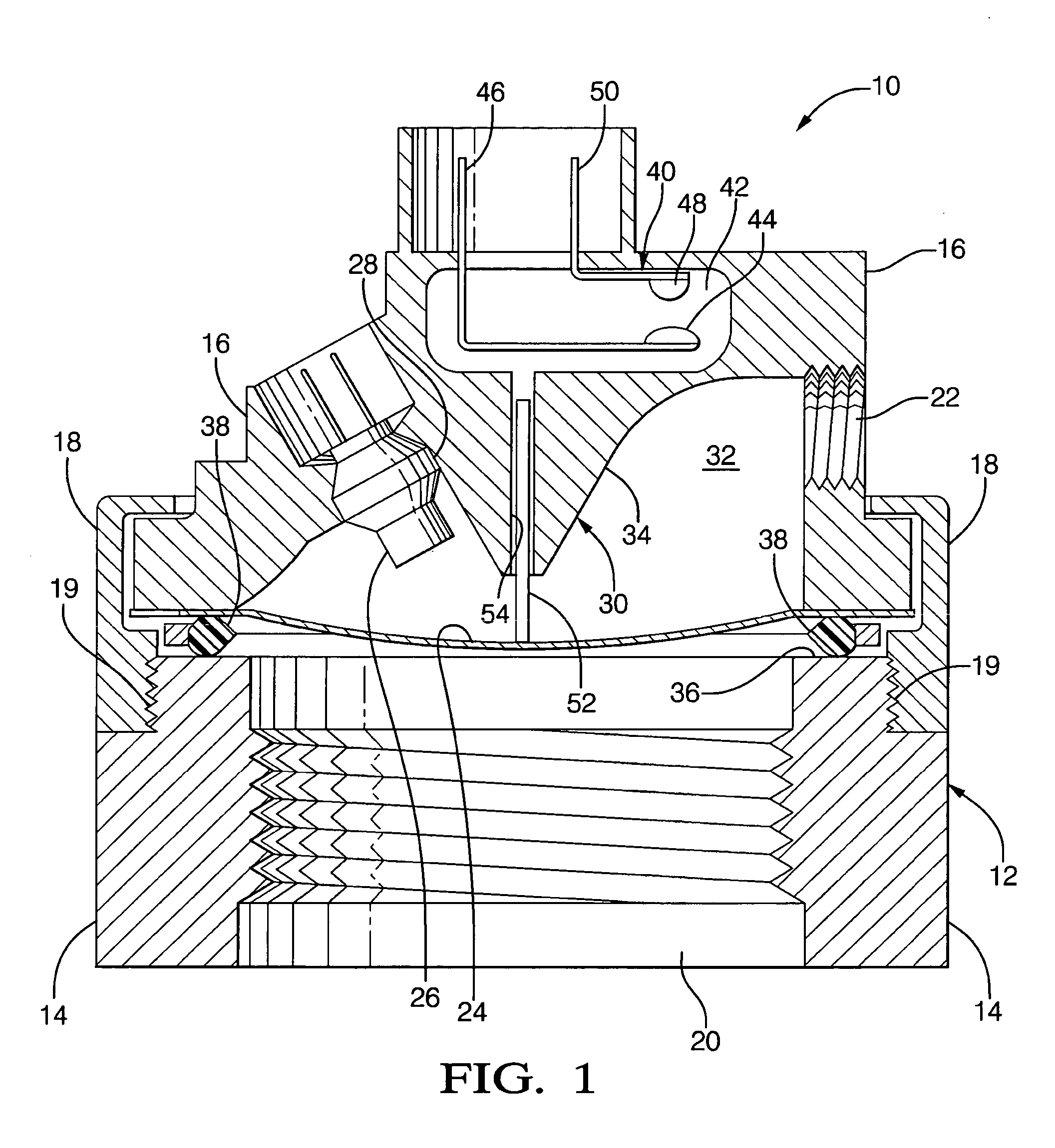
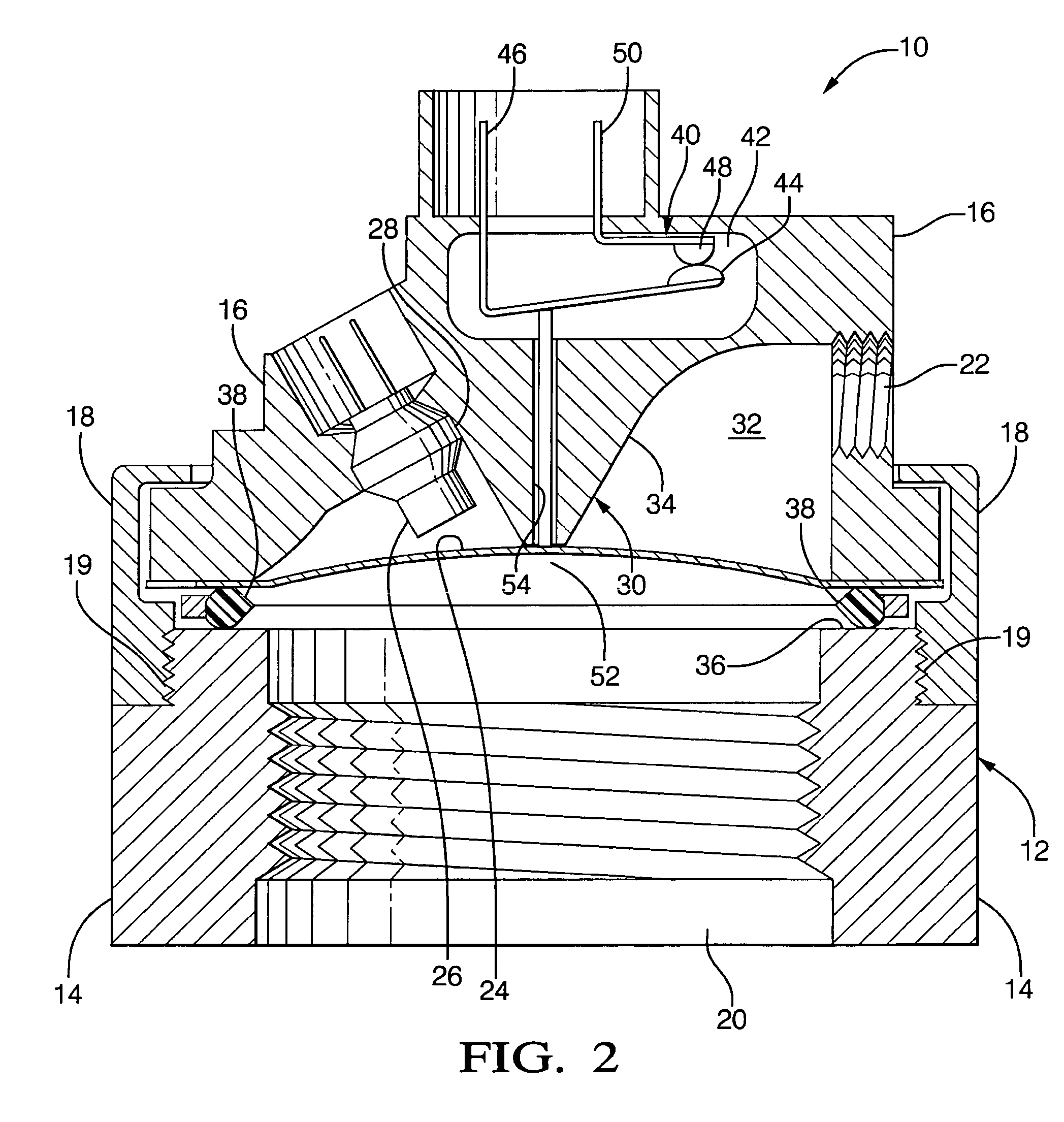
[0012] Referring to the Figures, wherein like numerals indicate like parts throughout the several views, a blowoff valve assembly is shown at 10 in FIG. 1.

[0013] A housing 12 preferably includes a first portion 14, a second portion 16, and a third portion 18. The first portion 14 of the housing 12 defines a refrigerant connection 20 for connection to a refrigerant. The second portion 16 of the housing 12 defines an ambient port 22 open to the atmosphere. A diaphragm 24 separates the refrigerant connection 20 from the ambient port 22. The diaphragm 24 is supported by the third portion 18 of the housing 12. The third portion 18 also serves to secure the second portion 16 to the first portion 14. Other configurations for the housing 12 are possible, aside from the portions 14, 16, 18 described herein.

[0014] The assembly 10 includes a squib 26. The second portion 16 of the housing 12 defines a seat 28 for housing the squib 26. The squib 26 is detonable in response to an event signal. ...


PUM


Abstract

A blowoff valve assembly includes a diaphragm separating a refrigerant connection from an ambient port open to the atmosphere. The refrigerant connection is preferably connected to air conditioning system such that the diaphragm is in contact with refrigerant from the system. The diaphragm is deflectable based on the pressure of the refrigerant and is operatively connected to a switch. When pressure of the refrigerant drops to a predetermined level, the diaphragm deflects to activate the switch. Additionally, the assembly also includes a detonable squib that explodes and ruptures the diaphragm, allowing the refrigerant to flow from the refrigerant connection to the atmosphere. Additional features, such as sensors for detecting refrigerant outside of the system, a collision subsystem, and an associated controller are also disclosed.

Description

CROSS-REFERENCE TO RELATED PATENT APPLICATION [0001] This application claims the benefit of provisional patent application Ser. No. 60 / 504,586 filed Sep. 18, 2003.TECHNICAL FIELD [0002] The subject invention relates to a blowoff valve assembly with an integrated pressure switch. BACKGROUND OF THE INVENTION [0003] Blowoff valve assemblies with integrated pressure switches are well known in the prior art. An example of such an assembly is disclosed in U.S. Pat. No. 5,153,396 (the '396 patent) to Cummings. [0004] The assembly of the '396 patent includes a diaphragm which separates a refrigerant connection for connection to a refrigerant from an ambient port open to atmosphere. The diaphragm senses the pressure of the refrigerant. A switch is operatively connected to the diaphragm and is closed when the pressure of the refrigerant is at a standard level. As pressure of the refrigerant increases to a predetermined lower threshold, the switch opens to shut down a compressor in an attempt ...

Claims


Application Information

Patent Timeline
IPC IPC(8): B60H1/00F16K17/16F25B41/04F25B49/00
CPCB60H1/00978F16K17/16F25B2700/1933F25B49/005F25B2500/222F25B41/04Y10T137/0368
Inventor MU, XIAOXIAECKSTEIN, TAYLOR R. JR.KUMPF, WILLIAM JAMESKADLE, PRASAD SHRIPAD
Owner DELPHI TECH INC
Why Eureka
Try Eureka