
Vacuum heat pump drying device

A drying device and vacuum heating technology, applied in the drying of solid materials, local stirring dryers, and static materials dryers, etc., can solve the problems of not inhibiting the growth of bacteria and microorganisms, affecting product quality, and high cost, and shortening the drying time. , low cost, good quality effect

Inactive Publication Date: 2011-10-26
胡日生
View PDF4 Cites 5 Cited by
  • Summary
  • Abstract
  • Description
  • Claims
  • Application Information

AI Technical Summary

Problems solved by technology

At present, most of the drying devices used at home and abroad use electric heating, steam or hot air heating, which has high temperature and high energy consumption.
Some people also use heat pumps for drying, but heat pump drying under medium and low temperature conditions cannot inhibit the growth of bacteria and microorganisms and affect product quality
There are also people who use a vacuum freeze dryer, and its biggest disadvantage is that it consumes a lot of energy and costs a lot.

Method used


Image

  • Vacuum heat pump drying device
  • Vacuum heat pump drying device

Examples


Embodiment Construction

[0007] The present invention is illustrated below by way of examples and accompanying drawings.

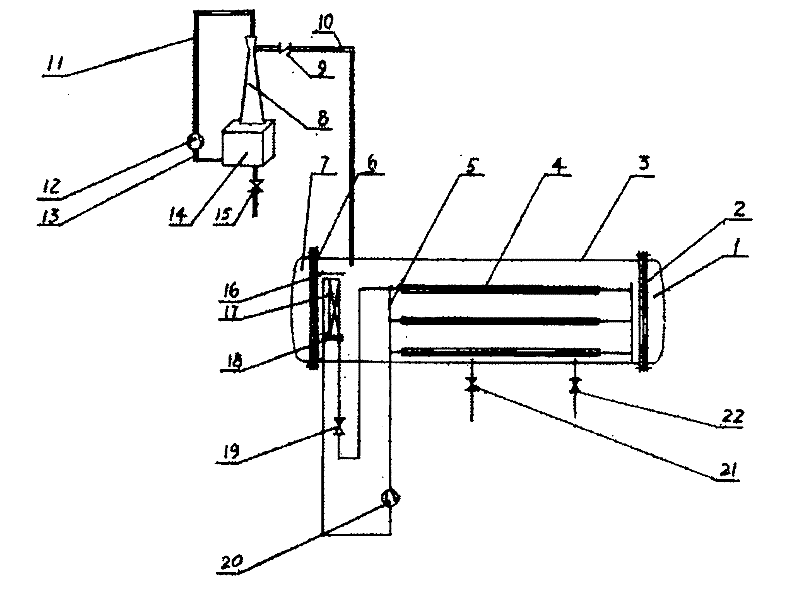
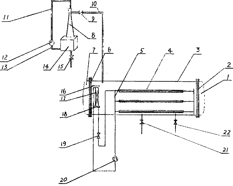
[0008] The vacuum heat pump drying device of the present invention has a drying box body 3, and its left and right ends have left and right end caps 7, 1 and left and right sealing strips 6, 2 respectively, and the condenser plate for exothermic heat of the heat pump is housed in the drying box body 3 The tube 5 and the evaporator coil hanger 16, the evaporator coil 17 and the water receiving tray 18 for the heat pump to absorb heat are installed on the evaporator coil hanger 16. The compressor 20 of the heat pump and the throttle valve 19 are arranged on the outside of the drying box body 3. The inlet and outlet of the compressor 20 are connected with the outlet of the evaporator coil 17 and the inlet of the condenser coil 5 respectively. , and the outlet communicate with the outlet of the condenser coil 5 and the inlet of the evaporator coil 17 respectively. The inner wall of t...


PUM


Abstract

The invention relates to a vacuum heat pump drying device, comprising a drying box body, wherein the left end and the right end of the drying box body are respectively provided with a left end cover and a right end cover as well as a left sealing strip and a right sealing strip, the box body is internally provided with a condenser coil pipe and an evaporator coil pipe lifting frame, the evaporator coil pipe lifting frame is provided with an evaporator coil pipe and a water receiving tray; the box body is externally provided with a compressor and a throttle, the inlet and the outlet of the compressor are respectively communicated with the outlet of the evaporator coil pipe and the inlet of the condenser coil pipe as well as the inlet and the outlet of the throttle are respectively communicated with the outlet of the condenser coil pipe and the inlet of the evaporator coil pipe; and a condenser coil pipe bracket is arranged on the inner side wall of the box body. The vacuum heat pump drying device is characterized in that a water ejector is arranged, the throat part of the water ejector is communicated with the box body by virtue of a check valve and a pipeline, the inlet of the water ejector is connected with the outlet of a high pressure water pump by virtue of a high pressure water pipeline, the inlet of the high pressure water pump is communicated with the lower part of a water tank by virtue of a water pipe, the lower part of the water tank is provided with a water escape valve, and the exterior below the drying box body is provided with a blowoff valve and an air intake valve. The vacuum heat pump drying device provided by the invention can be widely applied to industries requiring low temperature drying such as food industry, pharmaceutical industry, chemical industry and building material industry.

Description

technical field [0001] The invention relates to a drying device, in particular to a vacuum heat pump drying device. Background technique [0002] Drying is an operation with high energy consumption. How to improve energy efficiency, reduce costs, improve product quality and protect the environment is one of the focuses of professional scientists at home and abroad. At present, most of the drying devices used at home and abroad use electric heating, steam or hot air heating, which has high temperature and high energy consumption. There are also people who use heat pumps for drying, but heat pump drying can not inhibit the growth of bacteria and microorganisms under medium and low temperature conditions, which affects product quality. There are also people who use a vacuum freeze dryer. Its biggest disadvantage is high energy consumption and high cost. Contents of the invention [0003] The purpose of the present invention is to provide a vacuum heat pump drying device, wh...

Claims


Application Information

Patent Timeline
IPC IPC(8): F26B9/06F26B7/00F26B25/00
Inventor 胡日生
Owner 胡日生
Learn More