Evaporator core with a separable tube and a fin for a vehicle

Active Publication Date: 2005-03-24
HYUNDAI MOTOR CO LTD
View PDF13 Cites 12 Cited by
  • Summary
  • Abstract
  • Description
  • Claims
  • Application Information

AI Technical Summary

Benefits of technology

[0009] In a further preferred embodiment of the present invention, an evaporator core further comprises a fixing lever rotatably installed on a front end of a tank in order to prevent

Problems solved by technology

When an air conditioner is operated in a vehicle, there occurs a heat exchange between a coolant and a hot air, which results in condensation of water in an evaporator core.
In particular, since the conventional evaporator is arranged in a horizontal structure and is formed in an integral structure with a tube and a

Method used


Image

  • Evaporator core with a separable tube and a fin for a vehicle
  • Evaporator core with a separable tube and a fin for a vehicle
  • Evaporator core with a separable tube and a fin for a vehicle

Examples


Example

[0014] Hereinafter, such embodiments of the present invention are described in detail with reference to the accompanying drawings.

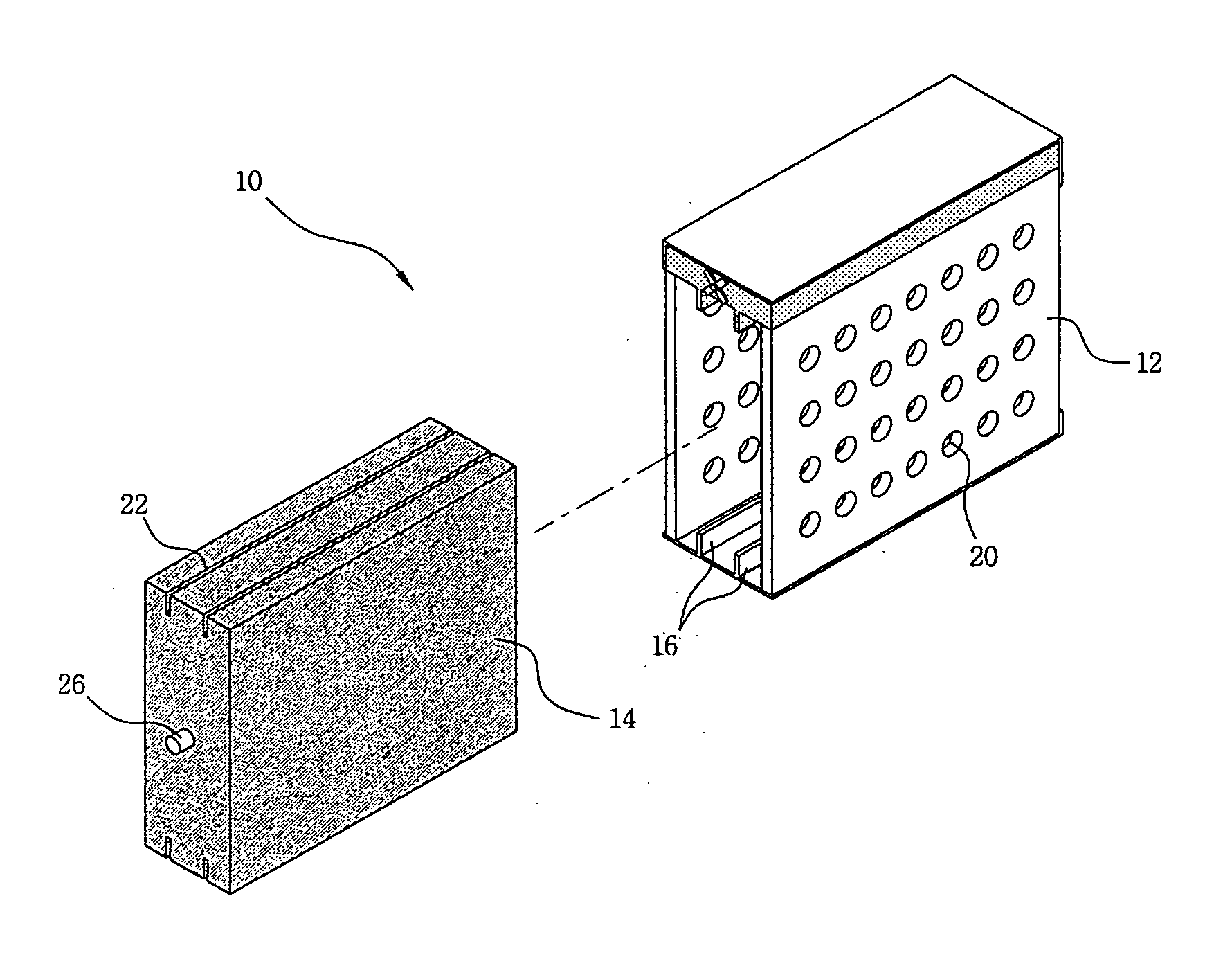
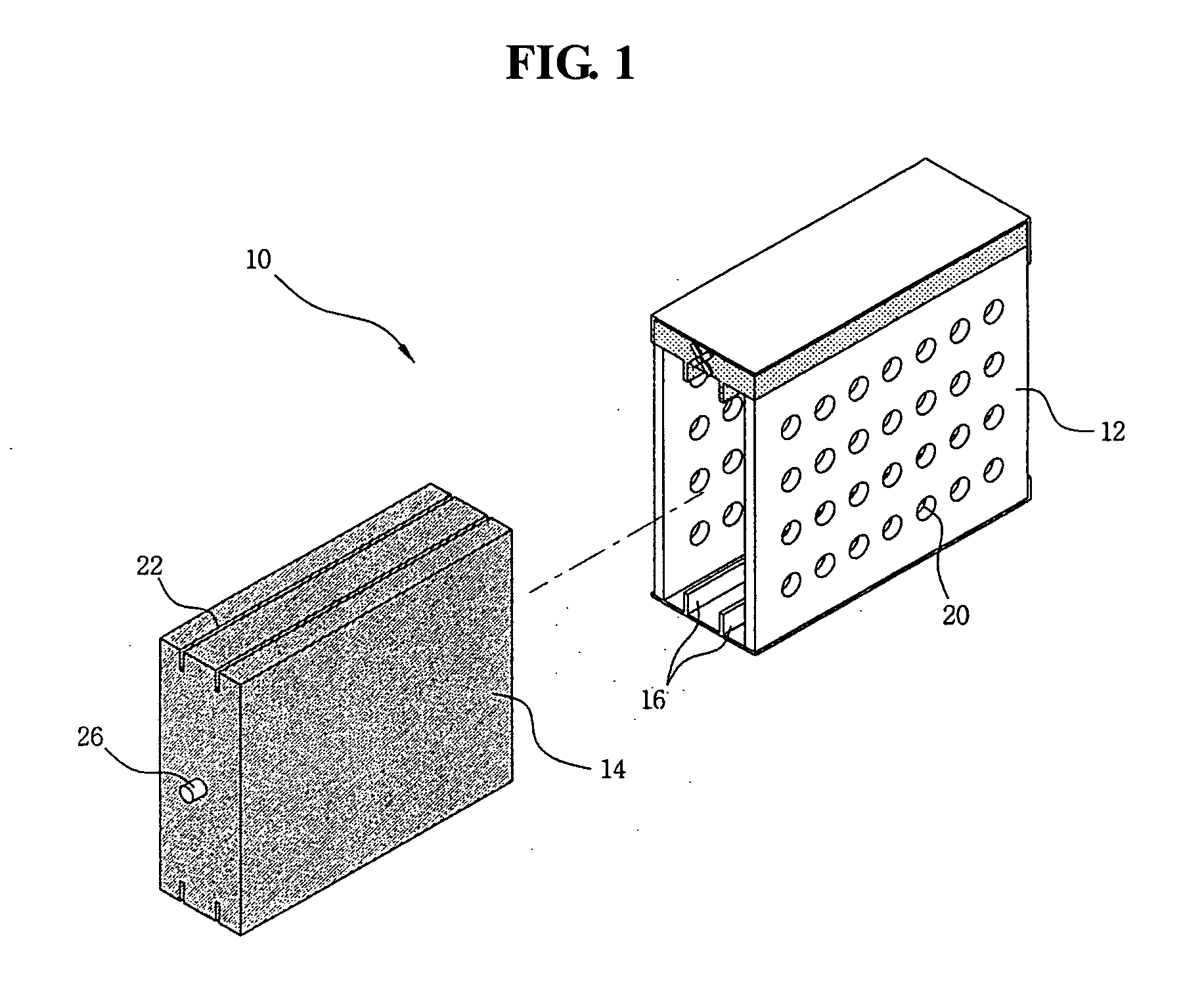
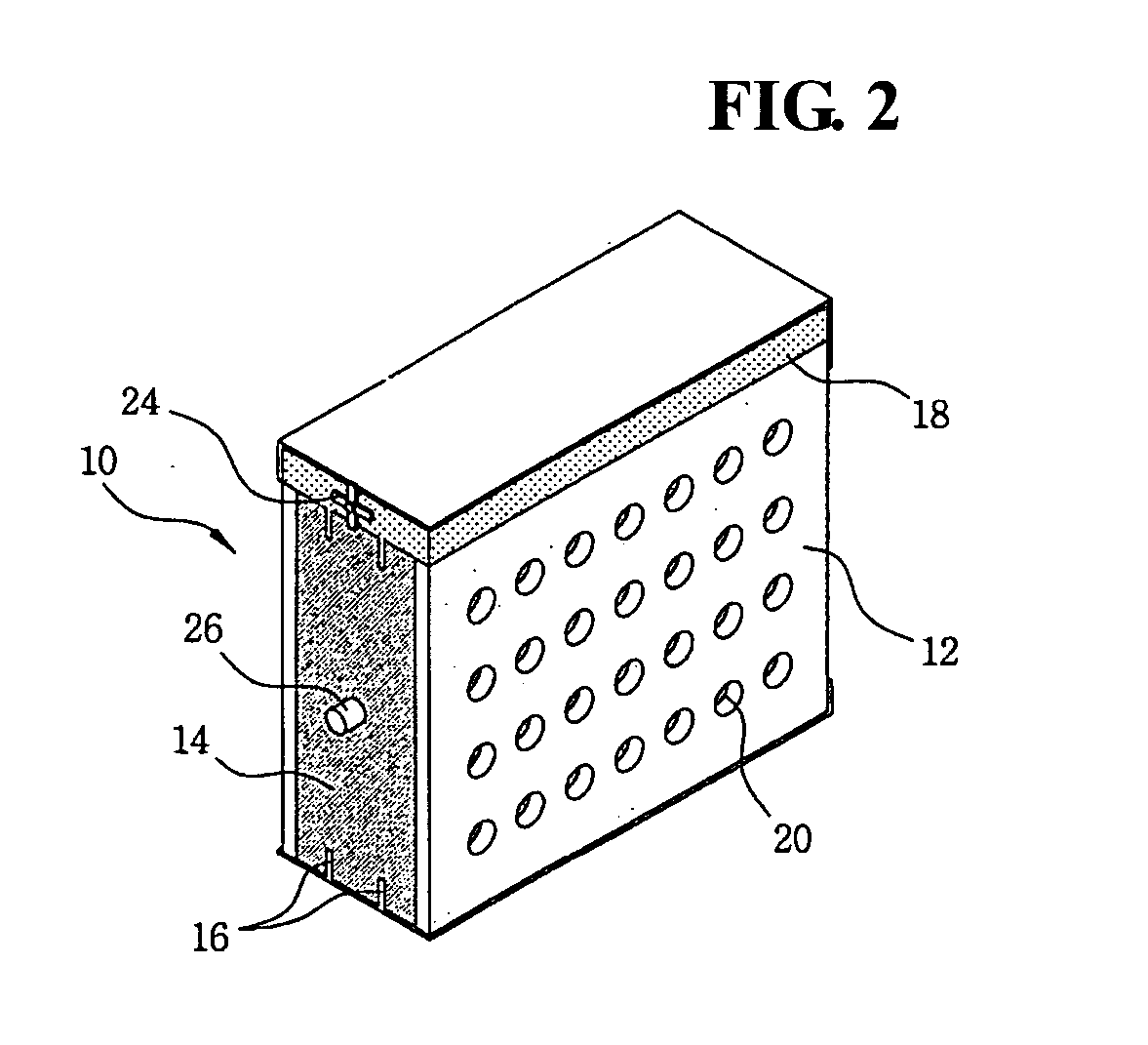
[0015] As shown in FIGS. 1-3, an evaporator 10 according to an embodiment of the invention includes a generally rectangular structure as a housing 12 and a fin assembly or bank of fins 14 that is received therein. The entire structure of the housing 12 may be formed as a hollow rectangular pipe. A guide rail 16 is installed at a bottom surface of the housing 12. Mounted at an uppermost portion of the housing 12 is a tank 18, fluidically communicating with the housing 12, wherein coolant flows into the tank 18.

[0016] The housing 12 is provided with a plurality of airflow holes 20 for heat exchange purposes. In particular, in the present invention, with the housing 12 being installed in a vertical direction as compared to the conventional housing installed in a horizontal direction, condensation water easily flows down for enhancing drainage.

[0017] A fix...


PUM


Abstract

An evaporator core includes a separable housing and a fin assembly. The housing is installed in such a manner that both sides of the housing are open, and a guide rail is installed on an upper surface and a bottom surface of the interior of the housing. A tank is integrally attached to an upper side of the housing and communicates with the housing. A fin assembly is installed in such a manner that the fin assembly slides along the guide rail of the housing for thereby being disengaged or engaged. A rain groove is formed in an upper and lower surface of the fin assembly.

Description

CROSS-REFERENCE TO RELATED APPLICATIONS [0001] This application claims priority of Korean Application No. 10-2003-0065756, filed on Sep. 23, 2003, the disclosure of which is incorporated fully herein by reference. FIELD OF THE INVENTION [0002] The present invention relates to an evaporator core with a separable tube and a fin for a vehicle, and, in particular, to such an evaporator core that is capable of enhancing drain operation of condensation water and maintaining a clean state of an air conditioner. BACKGROUND OF THE INVENTION [0003] A vehicle cooling apparatus generally comprises an evaporator, a compressor, a condenser, and an expansion valve. A coolant with a moderate temperature from a condenser is changed to a coolant of a low temperature and low pressure vapor as it passes through an expansion valve. The coolant is then vaporized into a gas at a low temperature and low pressure by the air generated by a blower as it passes through an evaporator. Finally, the coolant is va...

Claims


Application Information

Patent Timeline
IPC IPC(8): B60H1/32B60H1/00F25B39/02F25B47/00F25D21/14F28D1/03F28F1/32F28F9/00F28F9/013
CPCB60H1/00328F25B39/02F25B47/00F28F2280/02F28F1/32F28F9/001F28F9/013F25D21/14B60H1/32
Inventor CHOI, JAE SIK
Owner HYUNDAI MOTOR CO LTD
Why Eureka
Try Eureka