Muffling device and method for internal combustion engine

a technology of internal combustion engine and muffling device, which is applied in the direction of machines/engines, gas passages, gas chambers, etc., can solve the problems of attenuation, disadvantage, and different moving parts that generate noise, and achieve the effect of reducing the exhaust noise of internal combustion engines, reducing the number of decibels, and more design flexibility

Inactive Publication Date: 2005-03-24
SCHULTE FRANCIS
View PDF18 Cites 9 Cited by
  • Summary
  • Abstract
  • Description
  • Claims
  • Application Information

AI Technical Summary

Benefits of technology

Accordingly, a feature and advantage of the present invention is its ability to provide a device that substantially reduces exhaust noise from internal combustion engines.
is its ability to provide a device that substantially reduces exhaust noise from internal combustion engines.
Another feature and advantage of the present invention is that manufacturers will have more design flexibility, allowing decibels to be reduced without applying restrictive devices on the engines.
Still another additional feature and advantage of the present invention is that manufacturers can use louder conventional mufflers and still reduce the overall sound with the present invention, thus increasing horsepower of the engine.
Yet another further feature and advantage of the present invention is that, when utilized in combination with an All Terrain Vehicle, it enables the user to observe wildlife at closer proximity than is normally possible without the device.
Still yet another feature and advantage of the present invention is its ability to provide for a quiet approach by a motor vehicle.

Problems solved by technology

Internally, there are various moving parts that generate noise due to their interaction.
Thus there will be some attenuation due to this effect.
Although there are various engine muffling devices and methods available, each is disadvantageous when compared to the present invention.
The foregoing describes a traditional muffler type device used on vehicles, and, while adequate for some uses, particularly in urban areas where there is much surrounding noise, it falls short in achieving a level of quietness desirable for wilderness areas.
The Kempka et al. device is overly complicated as an add-on component to follow a standard muffler.
While generally simple in design, the Gerber device still requires more components than desirable.
Accordingly, the Ishida device requires several components, increasing the cost of manufacture.
However, the flared / conical exhaust outlet of Walsh will cause an augmentation of sound rather than a diminution thereof.

Method used


Image

  • Muffling device and method for internal combustion engine
  • Muffling device and method for internal combustion engine
  • Muffling device and method for internal combustion engine

Examples


Embodiment Construction

In describing the preferred and alternate embodiments of the present invention, as illustrated in the Figures, specific terminology is employed for the sake of clarity. The invention, however, is not intended to be limited to the specific terminology so selected, and it is to be understood that each specific element includes all technical equivalents that operate in a similar manner to accomplish similar functions.

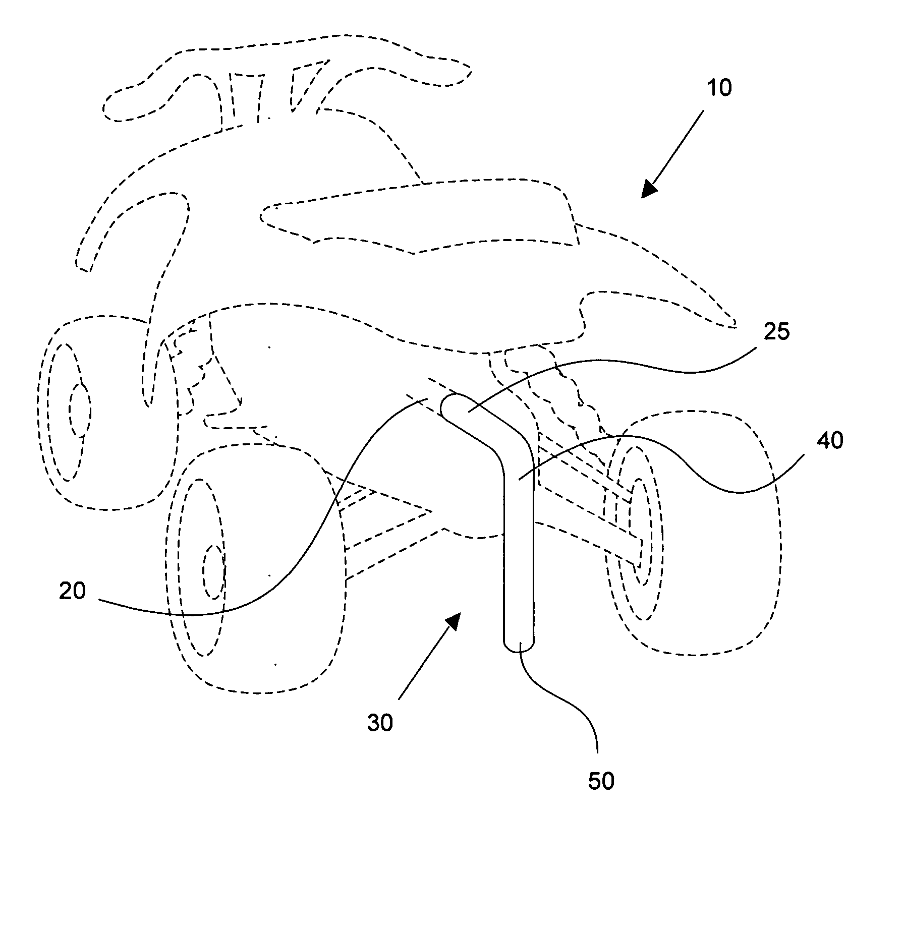
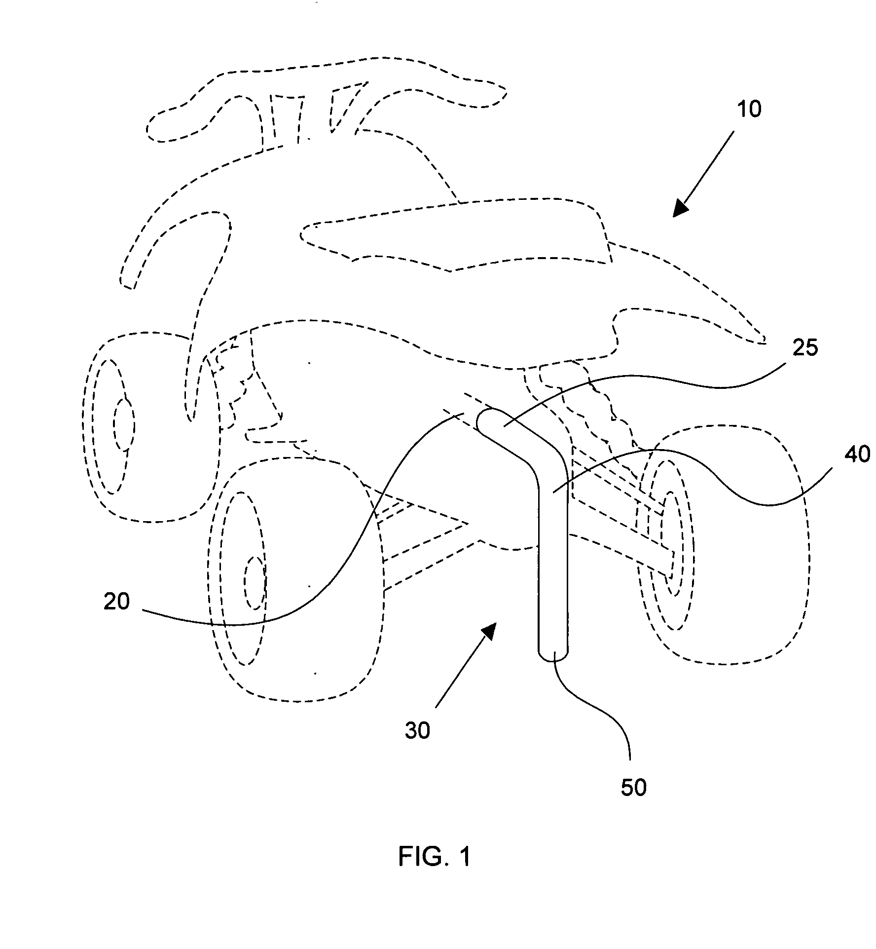
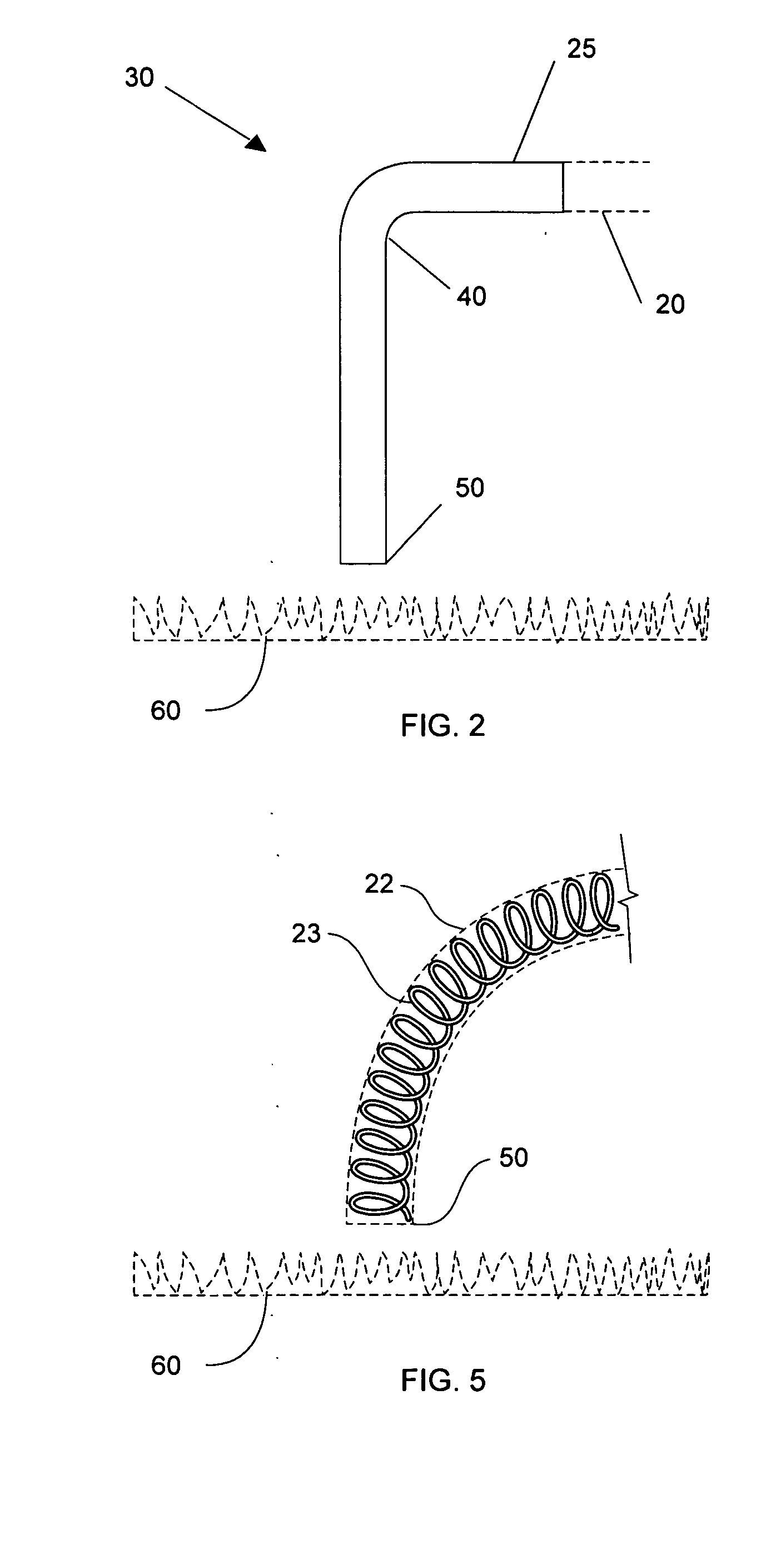
Referring now to FIGS. 1-2, muffling device 30 is preferably an elongated, generally cylindrically-shaped tube 22, formed from rubber, plastic, silicone rubber, metal, ceramic, or other suitable material. Tube 22 is of generally uniform diameter, but may comprise varying diameters. In the preferred embodiment, tube 22 comprises high temperature metal flex pipe extending from first end 25 through body 40 and terminating with high temperature silicone rubber at second end 50. Preferably tube 22 includes a fabric comprised of either synthetic or natural fiber woven and inc...


PUM

PropertyMeasurementUnit
angleaaaaaaaaaa
temperatureaaaaaaaaaa
diameteraaaaaaaaaa

Abstract

A device and method for muffling the sound from an internal combustion engine is described, wherein the device is a tube made of a suitable material such as rubber and is attached to the exhaust outlet of the vehicle. Further described is a method of muffling the sound of an internal combustion engine that is comprised of taking a length of tubing having a spring disposed therein, and attaching one end of the tubing to the outlet of the exhaust of an internal combustion engine, and directing the other end of the tubing toward the ground surface, by forming an approximate ninety degree bend, such that the second end of the tubing is in close proximity with the ground surface, with the result that the sound level of the exhaust from the engine is substantially reduced.

Description

TECHNICAL FIELD The present invention relates generally to a device and method for reducing the exhaust noise of internal combustion engines, and more particularly to a method and apparatus for muffling the exhaust noise of vehicles, including particularly, but not limited to, four-stroke internal combustion engines. BACKGROUND OF THE INVENTION Beginning with the early days of internal combustion engines, there has been an effort to reduce the sound levels that are produced during operation of these devices. Typically, there are various sources of sound that are produced during operation. As the fuel / air mixture is detonated, there is the sound generated by the explosion. Internally, there are various moving parts that generate noise due to their interaction. During intake and exhaust, there is also the sound of fluid rushing in or rushing out of the engine. While some of the noises emanate from the metal casing of the engine itself, a substantial portion of these sounds may be h...

Claims


Application Information

Patent Timeline
Patent Type & Authority Applications(United States)
IPC IPC(8): F01N1/00F01N13/08
CPCF01N1/00F01N2530/22F01N13/082
Inventor SCHULTE, FRANCIS
Owner SCHULTE FRANCIS
Why Eureka
Try Eureka