Seatbelt retractor and seatbelt device

a seatbelt and retractor technology, applied in the field of seatbelt retractors, can solve the problem of large shock from the seatbelt to the passenger, and achieve the effect of simple torque limiter mechanism structur

Inactive Publication Date: 2005-03-24
JOYSON SAFETY SYST JAPAN KK
View PDF3 Cites 17 Cited by
  • Summary
  • Abstract
  • Description
  • Claims
  • Application Information

AI Technical Summary

Benefits of technology

[0015] In the seatbelt retractors having the structures as described above according to the first to fourth aspects, the power transmission mechanism is connected to the locking member so as to transmit the power of the motor to the spool through the power transmission mechanism, the locking member, and the energy-absorbing mechanism. Accordingly, the spool rotates without receiving a resistance from the motor and the power transmission mechanism. As a result, the shock energy can be easily transmitted to the energy-absorbing mechanism, thereby effectively activating the energy-absorbing mechanism. With this structure, the shock energy exerted on a passenger can be effectively absorbed and lessened.
[0016] Also, the motor and the power transmission mechanism are disposed close to the locking mechanism of the EA mechanism, thereby increasing the versatility of possible layout features and design features of the retractor, including a design feature of a known retractor in which the motor and the power transmission mechanism are disposed close to the spool of the EA mechanism. Especially, according to the second aspect of the invention, the EA mechanism is formed of the torsion bar, thereby making the structure of the EA mechanism simple.
[0018] In the fourth aspect of the invention, the torque limiter mechanism is formed of the clutch, thereby making the structure of the torque limiter mechanism simple.

Problems solved by technology

In such an ELR, when the locking mechanism prevents the spool from rotating in the belt-withdrawing direction so that the seatbelt constrains and protects the passenger, the passenger receives a large shock from the seatbelt.

Method used


Image

  • Seatbelt retractor and seatbelt device
  • Seatbelt retractor and seatbelt device
  • Seatbelt retractor and seatbelt device

Examples


Embodiment Construction

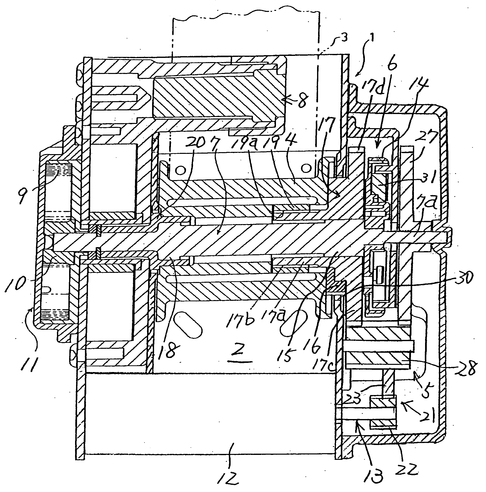
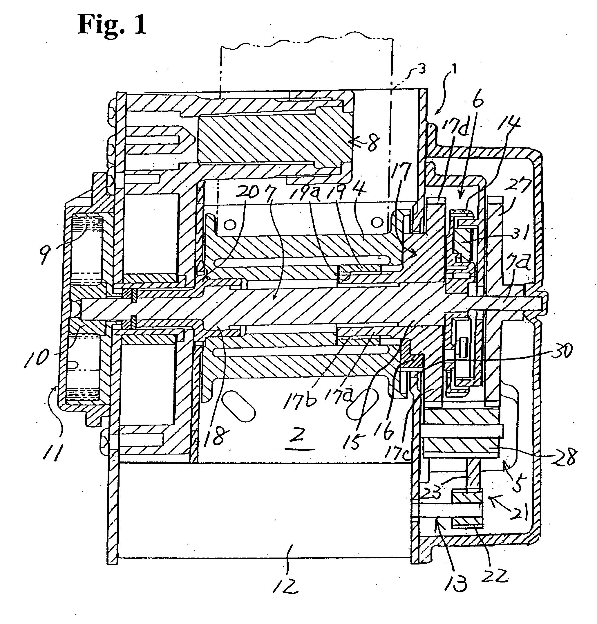
[0028] Hereunder, embodiments the present invention will be described below with reference to the drawings. FIG. 1 is a schematic sectional view of a seatbelt retractor according to an embodiment of the present invention. FIG. 2 is an exploded perspective view showing the seatbelt retractor shown in FIG. 1. FIG. 3 is an exploded perspective view showing a part of the seatbelt retractor shown in FIG. 1.

[0029] As shown in FIGS. 1 to 3, a seatbelt retractor 1 is an ELR and is mainly formed of a C-shaped frame 2; a seatbelt 3; a spool 4 rotatably supported between sidewalls of the C-shaped frame 2 for retracting the seatbelt 3; deceleration-sensing means 5 to be activated upon sensing large car deceleration in case of emergency; a locking mechanism 6 to be activated by the deceleration-sensing means 5 for preventing at least the spool 4 from rotating in a belt-withdrawing direction; a torsion bar 7 loosely fit into the center of the spool 4 in the axial direction thereof for rotatably ...


PUM


Abstract

A seatbelt retractor includes a spool for winding a seatbelt; a locking mechanism having a locking member rotatable together with the spool in a normal condition and being prevented from rotating in a seatbelt-withdrawing direction in an emergency condition; an energy-absorbing mechanism interposed between the spool and the locking member for absorbing shock energy exerted on a passenger when the spool rotates in the seatbelt-withdrawing direction relative to the locking member in the emergency condition; and a motor for generating power to rotate the spool. A power transmission mechanism is connected to the locking member for transmitting the power of the motor to the spool through the power transmission mechanism, the locking member, and the energy-absorbing mechanism.

Description

BACKGROUND OF THE INVENTION AND RELATED ART STATEMENT [0001] The present invention relates to a seatbelt retractor for retracting a seatbelt to constrain and protect a passenger in a vehicle such as an automobile. More specifically, the present invention relates to a seatbelt retractor capable of controlling a belt tension of the seatbelt by rotating a spool with a motor power and having an energy-absorbing mechanism (hereinafter, also referred to as EA mechanism) for absorbing shock energy exerting on a passenger caused by the seatbelt when the seatbelt is prevented from being withdrawn in a case, for example, where a car undergoes large deceleration due to a crash or the like. The present invention also relates to a seatbelt device provided with the seatbelt retractor. [0002] A seatbelt apparatus attached to a seat in a vehicle such as an automobile includes a seatbelt retractor for retracting a seatbelt on a spool. As such a retractor, a variety of emergency locking retractors (h...

Claims


Application Information

Patent Timeline
Patent Type & Authority Applications(United States)
IPC IPC(8): B60R22/28B60R22/34B60R22/46B60R22/48
CPCB60R22/3413
Inventor INUZUKA, KOJITANAKA, KOJI
Owner JOYSON SAFETY SYST JAPAN KK
Why Eureka
Try Eureka