
Hockey playing table

Inactive Publication Date: 2005-03-24
ACAS DESIGN
View PDF5 Cites 6 Cited by
  • Summary
  • Abstract
  • Description
  • Claims
  • Application Information

AI Technical Summary

Benefits of technology

[0007] Another objective of the present invention is to provide a hockey playing table, wherein when the doll is worn out or broken, the doll can be directly replaced, thereby facilitating replacement and maintenance of the doll.
[0008] A further objective of the present invention is to provide a hockey playing table, wherein the doll is moved and rotated on the platform by attraction of the magnet seat of the rotor, so that it is unnecessary to form slots in the platform, thereby enhancing the aesthetic quality of the hockey playing table.

Problems solved by technology

However, when the doll 12 is worn out or broken, the worker has to dismantle the platform 15 so as to remove the doll 12 from the platform 15 for replacement, thereby causing inconvenience in replacement and maintenance of the doll 12.
In addition, it is necessary to form slots 11 in the platform 15, thereby decreasing the aesthetic quality of the conventional hockey playing table.

Method used


Image

  • Hockey playing table
  • Hockey playing table
  • Hockey playing table

Examples


Embodiment Construction

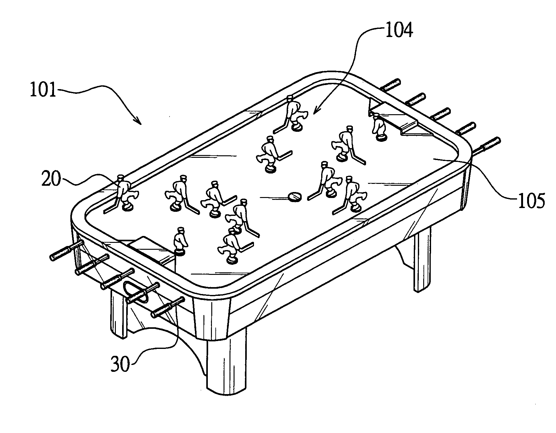
[0027] Referring to the drawings and initially to FIGS. 1-4, a hockey playing table 101 in accordance with the preferred embodiment of the present invention comprises a platform 105, and a plurality of manipulation mechanisms 104 mounted on the platform 105.

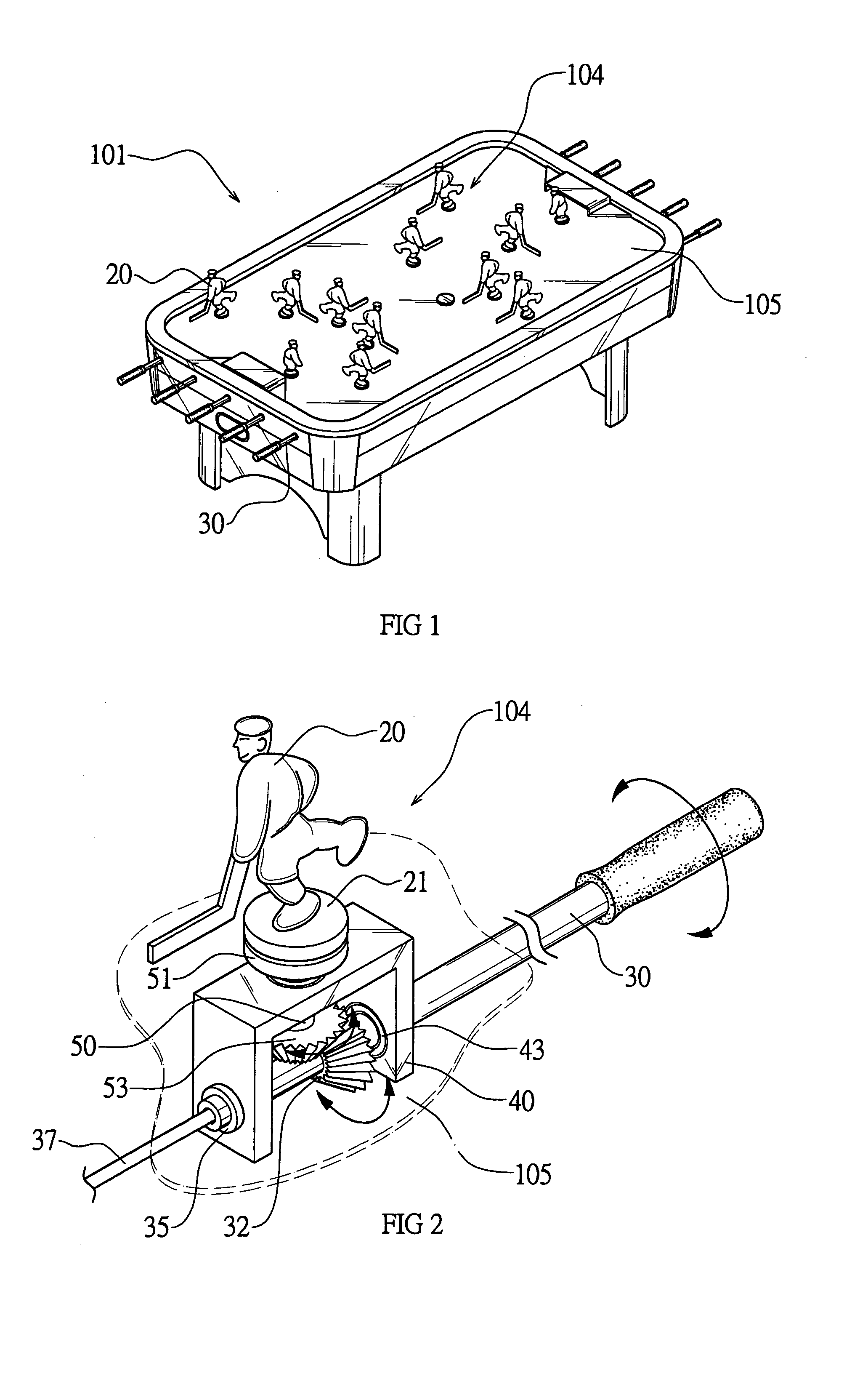
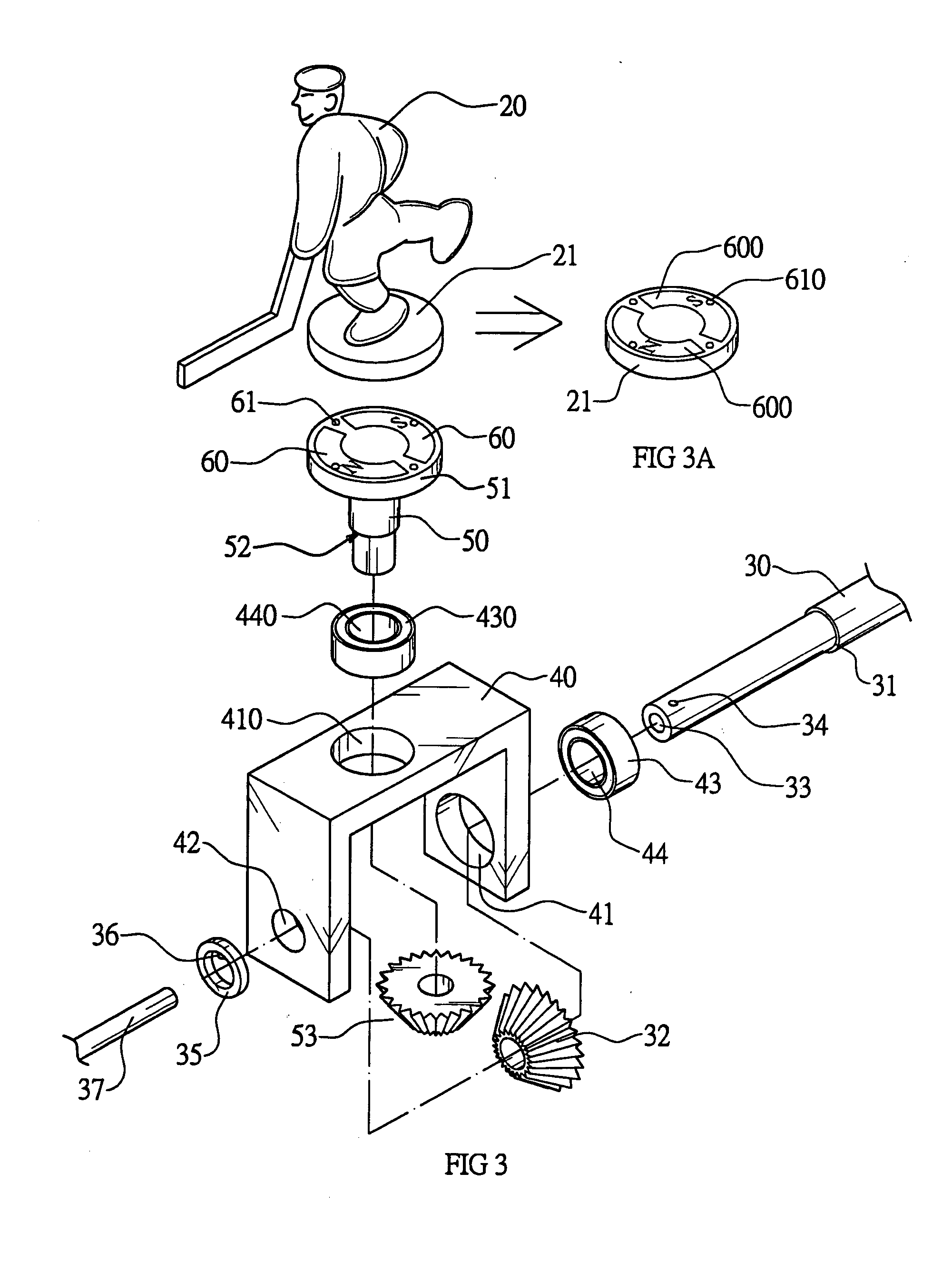
[0028] Each of the manipulation mechanisms 104 includes a connecting rack 40, an operation rod 30, a rotor 50, and a doll 20.

[0029] The connecting rack 40 is mounted in the platform 105. The connecting rack 40 is substantially inverted U-shaped, and has a first side wall formed with a first insertion hole 41 for mounting a first bearing 43, a second side wall formed with a through hole 42 and a top wall formed with a second insertion hole 410 for mounting a second bearing 430. The first bearing 43 is formed with a through hole 44, and the second bearing 430 is formed with a through hole 440.

[0030] The operation rod 30 is rotatably mounted on the connecting rack 40 and is extended through the through hole 44 of the first bearin...


PUM


Abstract

A hockey playing table includes a platform, and a plurality of manipulation mechanisms mounted on the platform. Each of the manipulation mechanisms includes a connecting rack, an operation rod, a first bevel gear, a rotor, a second bevel gear, and a doll. Thus, the rotor has an upper end formed with a magnet seat, and the doll has a lower end formed with a magnet seat attracted by and moved with the magnet seat of the rotor, so that when the rotor is rotated by rotation of the operation rod, the doll is rotated by rotation of the rotor.

Description

BACKGROUND OF THE INVENTION [0001] 1. Field of the Invention [0002] The present invention relates to a hockey playing table, and more particularly to a hockey playing table that can achieve the effect of playing the hockey game. [0003] 2. Description of the Related Art [0004] A conventional hockey playing table in accordance with the prior art shown in FIGS. 7 and 8 comprises a platform 15 having a top formed with a plurality of elongated slots 11, a ball inlet 10 mounted on a side plate of the platform 15, a ball outlet 14 mounted on the side plate of the platform 15, and a plurality of manipulation mechanisms mounted on the platform 15. Each of the manipulation mechanisms includes an operation rod 13 rotatably mounted on the platform 15, a connecting rack 19 mounted on the operation rod 13, a first bevel gear 18 secured on the operation rod 13 to rotate therewith, a rotor 16 rotatably mounted on the connecting rack 19 and movably mounted in the respective slot 11 of the platform 1...

Claims


Application Information

Patent Timeline
IPC IPC(8): A63F7/00A63F7/06A63F7/07
CPCA63F7/0088A63F7/0684A63F7/0672
Inventor TIEN, FENG-YI
Owner ACAS DESIGN
Learn More