Plasma display apparatus

a technology of display apparatus and plasma, which is applied in the direction of gas discharge vessel/container, gas-filled discharge tube, electrodes, etc., can solve the problem that the loss of discharge energy is a significant factor in power consumption

Inactive Publication Date: 2005-03-24
RAKUTEN GRP INC
View PDF19 Cites 14 Cited by
  • Summary
  • Abstract
  • Description
  • Claims
  • Application Information

AI Technical Summary

Problems solved by technology

In PDPs, loss of discharge energy is a significant factor for power consumption.

Method used


Image

  • Plasma display apparatus
  • Plasma display apparatus
  • Plasma display apparatus

Examples


first embodiment

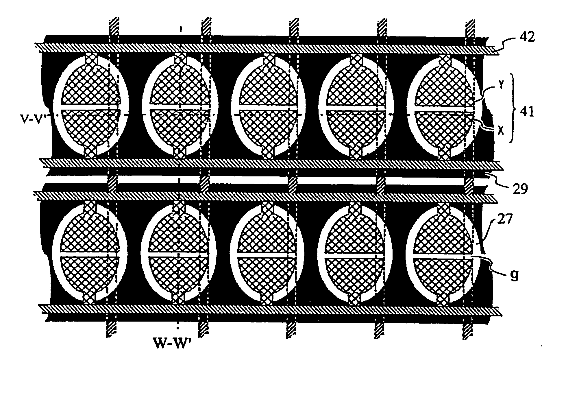
[0034]FIG. 6A is a top view showing in part the construction of a PDP according to a first embodiment of the present invention, and FIGS. 6B and 6C are sectional views taken along, respectively, the lines W-W′ and V-V′ of FIG. 6A.

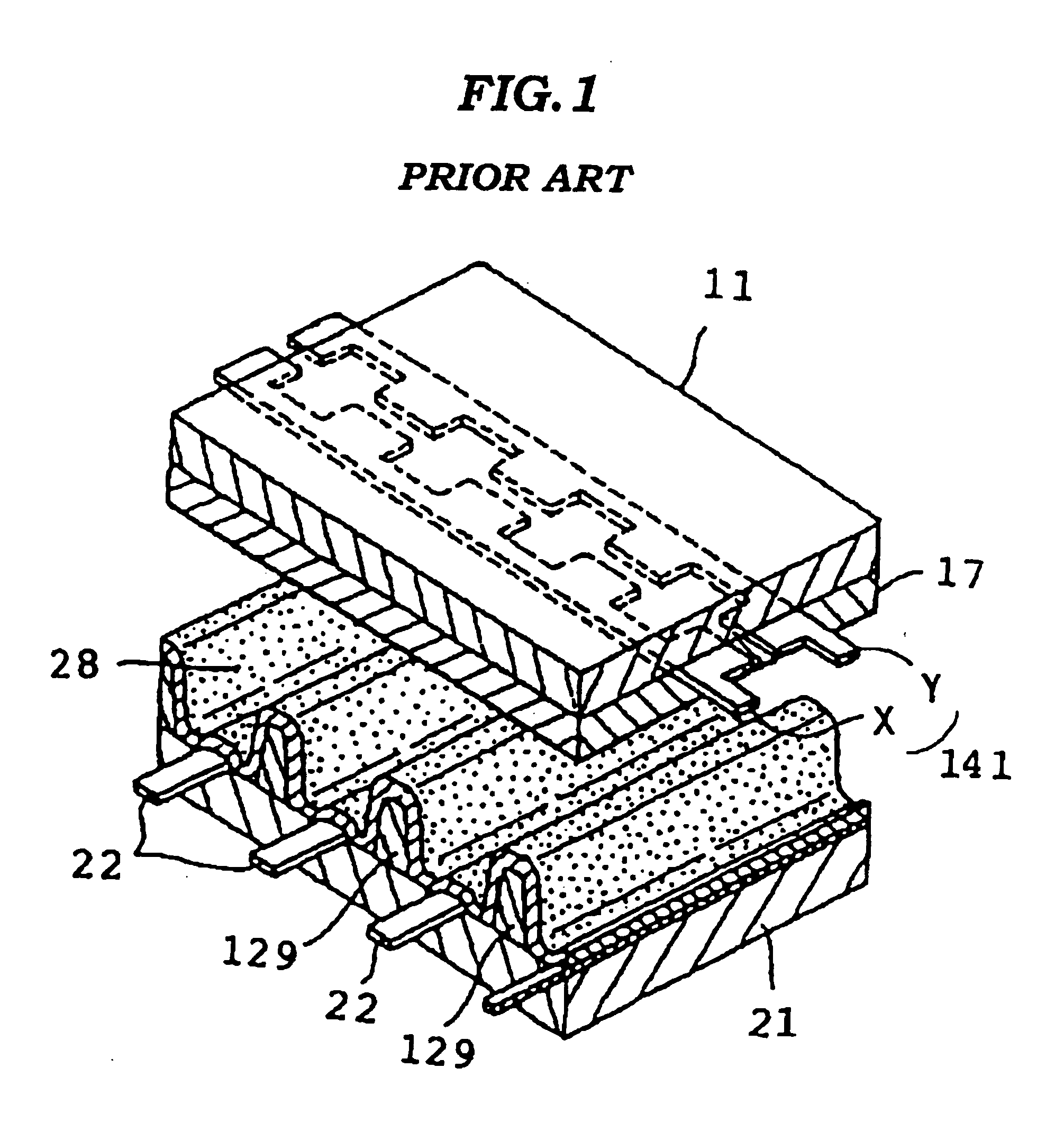
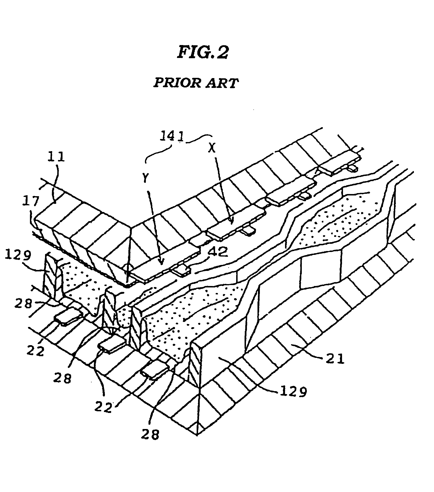
[0035] Referring to FIGS. 6A, 6B, and 6C, the PDP includes a plurality of display element electrodes, one of which is indicated by the reference numeral 41. The display element electrode 41 is constituted of a pair of semicircular or semielliptical electrode segments X and Y, and is formed in a shape similar to the shape of a discharge area. The display element electrode 41 serves to cause a discharge in the associated one of a plurality of cells 27 defined by a barrier structure. 29. The inner surface of the barrier structure 29 is coated with a phosphor member 28 which cause luminescence in response to a discharge of the display element electrode 41. The PDP also includes a plurality of address electrodes, one of which is indicated by the reference numer...

second embodiment

[0039]FIG. 10 is a top view showing in part the construction of a PDP according to a second embodiment of the present invention. As shown in FIG. 10, the PDP according to the second embodiment has display element electrodes 41 constituted of a pair of trapezoidal electrodes and the barrier structure 29 of which width is varied in accordance with the shapes of the display element electrodes. The barrier structure 29 defines cells 27 having channel in the column direction. The channel passing through each of the cells 27 in the column direction facilitates the evacuation process to introduce ionizable gas in between the front substrate 11 and the back substrate 21.

third embodiment

[0040]FIG. 11 is a top view showing in part the construction of a PDP according to a third embodiment of the present invention. Referring to FIG. 11, in the PDP according to the third embodiment, each of the cells 27 is arranged closely to achieve higher density of cells, thereby enhancing brightness of the PDP. The address electrode 22 is arranged so as to extend along left end and right side of the cells of alternately row by row. The cells may be arranged so that a set of R, G, and B cells forms a triangle, i.e., in a delta arrangement, so that interlacing may be used for operation.

[0041]FIG. 12 and FIG. 13 are top views showing modifications of the third embodiment. In the PDP shown in FIG. 12, the display element electrode 41 is constituted of a pair of substantially triangular electrode segments, and the bus electrode 42 is formed on top of the top surface of the barrier structure 29 so as not to overlap the cells. In the PDP shown in FIG. 13, the display element electrode 41...


PUM


Abstract

A plasma display apparatus includes a plurality of display element electrodes each constituted of a pair of electrode segments having linear edges opposing each other, with a predetermined distance provided therebetween, the width of each of the electrode segments becoming narrower in the direction away from the associated one of the linear edges. The plasma display apparatus also includes a barrier structure, the inner surfaces of which being disposed along the outer ends of the plurality of display element electrodes and thereby defining a plurality of cells each of which is to be activated by the associated one of the plurality of display element electrodes so as to emit light. In the plasma display apparatus, ultraviolet rays caused by a discharge are efficiently transmitted to phosphor members on the surfaces of cells to emit light with a reduced loss of energy.

Description

BACKGROUND OF THE INVENTION [0001] 1. Field of the Invention [0002] The present invention generally relates to plasma display apparatuses, and more specifically, the present invention relates to a plasma display apparatus in which the efficiency of emission of light is improved. [0003] 2. Description of the Related Art [0004]FIG. 1 is an exploded perspective view showing the construction of an AC plasma display panel (hereinafter abbreviated as PDP) disclosed in U.S. Pat. No. 5,640,068. Referring to FIG. 1, the PDP includes a plurality of display electrodes, only one of which is shown and is indicated by the reference numeral 141. The display electrode 141 extends in the row direction of the PDP. The display electrode 141 is constituted of a pair of electrodes X and Y having edges opposing each other. The display electrode 141 is formed on a front substrate 11, and is covered by a dielectric layer 17. The surface of the dielectric layer 17 is covered by a protective MgO film. The PD...

Claims


Application Information

Patent Timeline
Patent Type & Authority Applications(United States)
IPC IPC(8): H01J11/12H01J11/14H01J11/22H01J11/24H01J11/26H01J11/32H01J11/34H01J11/36H01J11/42
CPCH01J11/12H01J11/24H01J2211/365H01J2211/245H01J11/36H01J11/42
Inventor SANO, KOMORIKAWA, KAZUTOSHI
Owner RAKUTEN GRP INC
Why Eureka
Try Eureka