Digital predistortion for power amplifier

a technology of predistortion and power amplifier, applied in the field of amplifiers, can solve the problems of the adaptability of the predistortion applied to the amplifier to the change of the amplifier, and achieve the effect of compensating amplifier distortion and being simple to implemen

Active Publication Date: 2005-03-24
NORTHROP GRUMMAN SYST CORP
View PDF4 Cites 10 Cited by
  • Summary
  • Abstract
  • Description
  • Claims
  • Application Information

AI Technical Summary

Benefits of technology

[0008] It will be appreciated from the foregoing that the present invention represents a significant advance over amplifier predistortion techniques used in the past. In particular, the present invention achieves compensation for amplifier distortion by computing predistortion parameters based on measurements of R

Problems solved by technology

Therefore, the amount of predistortion applied to the amplifier adapts to ampl

Method used


Image

  • Digital predistortion for power amplifier
  • Digital predistortion for power amplifier

Examples


Embodiment Construction

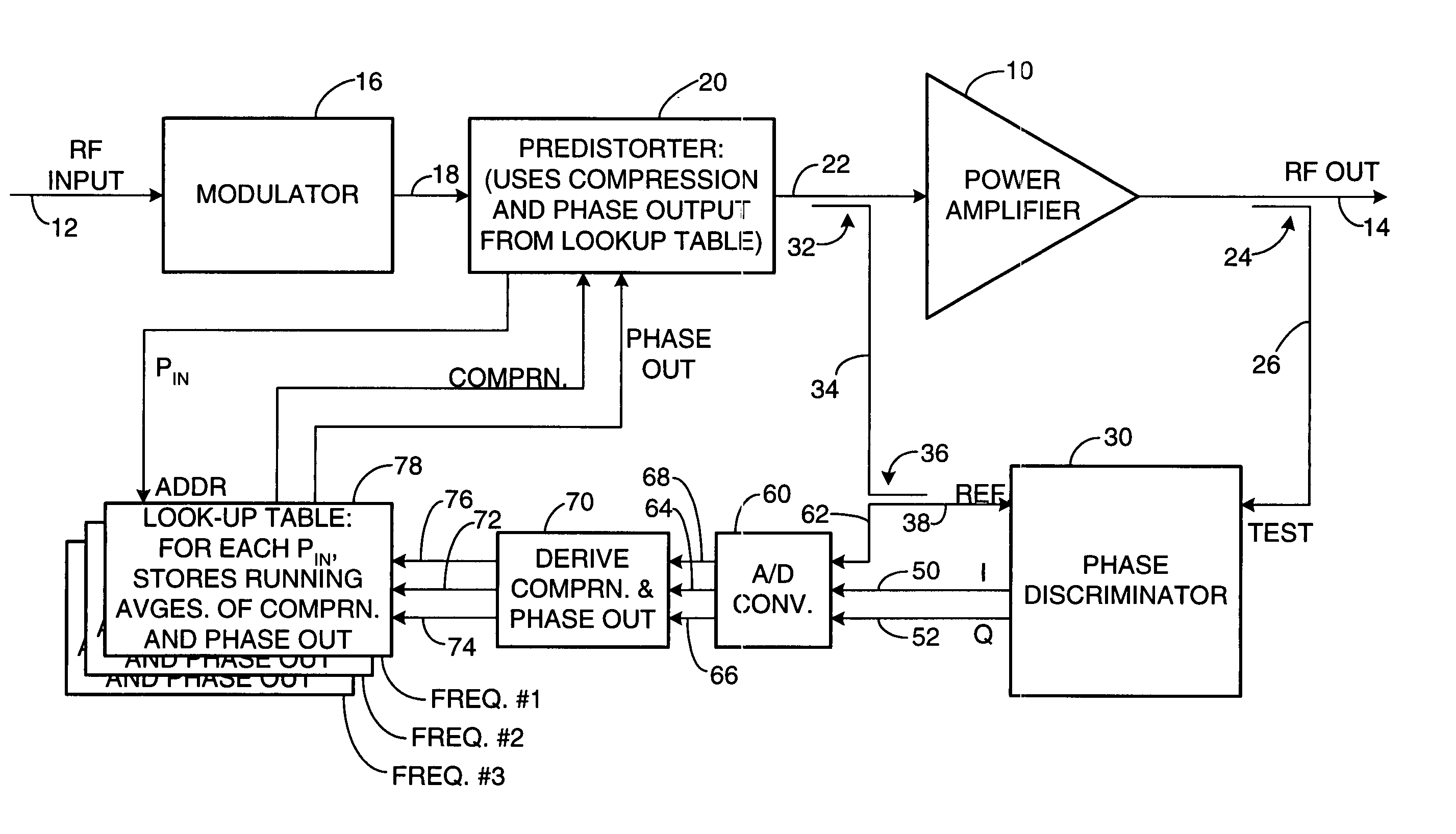
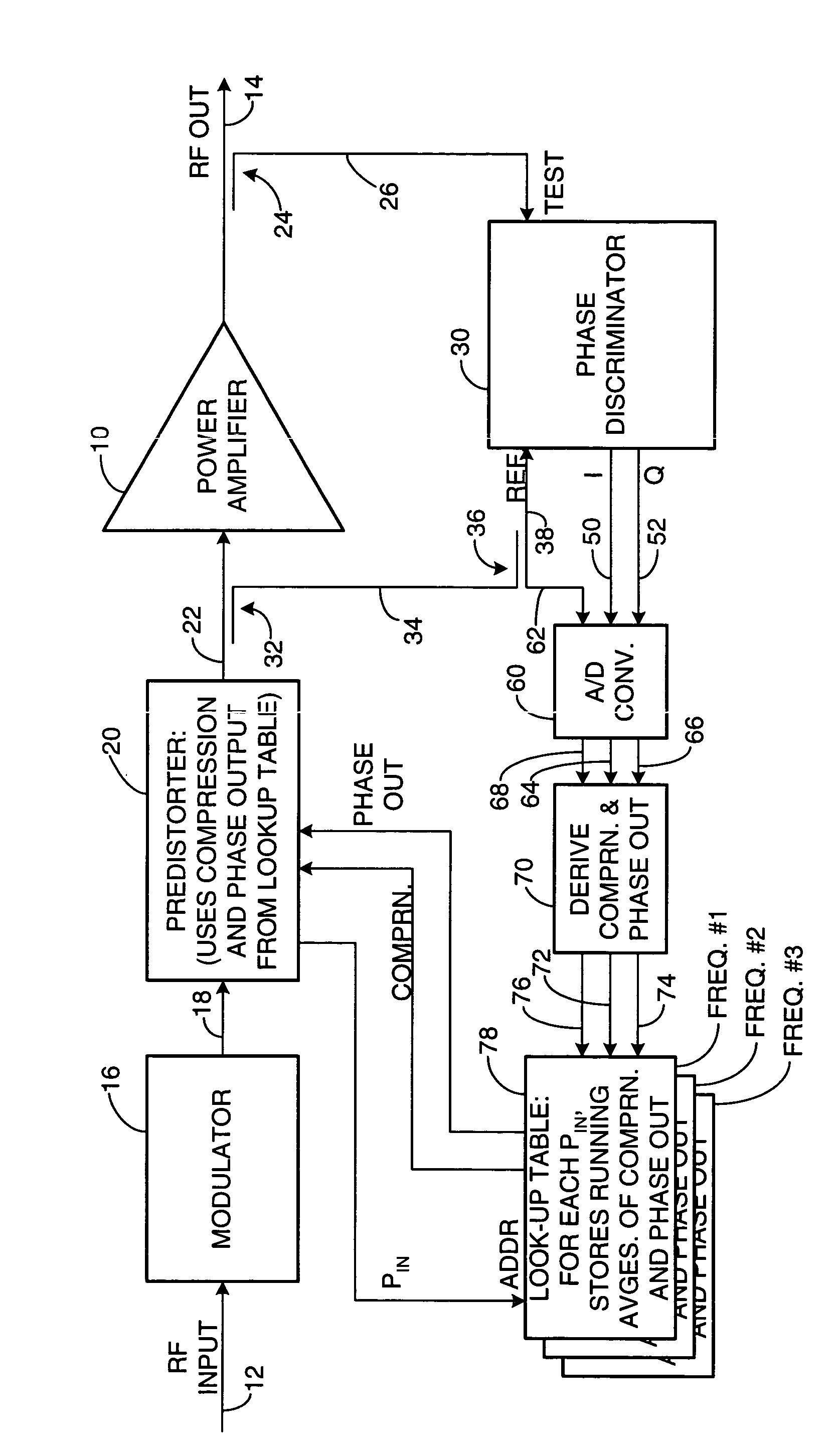
[0010] As shown in the drawing for purposes of illustration, the present invention pertains to a predistortion technique for use in power amplifiers for radio-frequency (RF) transmitters. A power amplifier is subject to unwanted distortion in both the phase and amplitude of its output when operated outside its generally linear characteristic that governs operation at relatively low input and output powers. Predistortion of the input signal has been proposed as a solution extending the linear region of operation of an amplifier. U.S. Pat. No. 5,867,065 discloses a predistortion technique that compares input and output digital signals at baseband frequencies. This approach requires complex supporting circuitry, including local oscillators, a downconverter and a demodulator to convert the amplifier RF output signal back to baseband for comparison with the input signals.

[0011] In accordance with the present invention, an RF power amplifier is subject to predistortion directly, at the f...


PUM


Abstract

Apparatus and a corresponding method for predistorting an input signal applied to a radio frequency (RF) power amplifier, to compensate for amplifier distortion at high powers. The RF amplifier input and output signals are continuously monitored and difference signals are generated in an RF phase discriminator. The difference signals are converted to digital form and stored in a lookup table in the form of running averages of an RF amplifier gain compression value and an RF amplifier output phase value for each observed RF input power value. A predistorter module retrieves these values and predistorts the RF amplifier input by way of compensation.

Description

BACKGROUND OF THE INVENTION [0001] The present invention relates generally to amplifiers and, more particularly, to power amplifiers used in communication systems, such as in base stations of two-way communications systems. It is well known that power amplifications stages of typical radio frequency (RF) transmitters behave in a nonlinear fashion when operated near peak capacity. Amplifiers have a linear region of operation at low powers. That is to say, at low input and output powers, the power of the output signal is linearly related to the power of the input signal. As an amplifier is driven at increasing power levels, a graph relating its output and input powers exhibits a characteristic “drop-off” and the output power is no longer linearly related to the input power. [0002] A simple solution to this problem is to require that the power amplifier be operated only in the linear region below its saturation point. Backing off a power amplifier in this fashion requires that a larger...

Claims


Application Information

Patent Timeline
IPC IPC(8): H03F1/32
CPCH03F1/3247
Inventor SCHREYER, GEORGE W.BECKER, JAMES C.
Owner NORTHROP GRUMMAN SYST CORP
Why Eureka
Try Eureka