Liquid container

a liquid container and lid technology, applied in printing and other directions, can solve the problems of reducing the reliability of the ink container, difficult to attach the lid portion, and a lot of trouble in the operation of forming the ink cartridge, so as to achieve the effect of reducing the number of components and facilitating and reliably performing

Inactive Publication Date: 2005-03-24
SEIKO EPSON CORP
View PDF25 Cites 12 Cited by
  • Summary
  • Abstract
  • Description
  • Claims
  • Application Information

AI Technical Summary

Benefits of technology

[0023] According to this invention, the bonding of a film by heat welding can be easily and reliably performed without deposition failure or the like.
[0024] In this liquid container, a liquid lead-out opening is formed at the end portion of the lead-out member, and the opening of the lead-out member and the gap are sealed with the single sealing member bonded to the outer surface of the casing. According to this invention, the sealing of the opening of the lead-out member and the sealing of the gap between the opening portion of the casing and the lead-out member can be performed in the same step. Furthermore, the number of components can be reduced.
[0025] The liquid container of the invention is a liquid container comprising a first casing having an opening portion, and a second casing that is attached to the first casing and closes the opening portion of the first casing, wherein the first casing includes at least one first engaging means, and the second casing includes at least one second engaging means that engages the first engaging means, the configuration being such that the first engaging means includes a first guide portion that guides the second engaging means when the first engaging means engages the second engaging means, and such that the second engaging means has flexibility.
[0026] According thereto, when the second casing is attached to the first casing, the second engaging means is guided by the first guide portion, thereby enabling smooth attachment. Besides, on this occasion, since having flexibility, the second engaging means can bends slightly upon attachment. Thereby, even when the second engaging means, for example, is formed slightly shifted widthwise or lengthwise of the first casing relative to the first engaging means due to a manufacturing error caused upon manufacture of the second engaging means, the second engaging means can engage the first engaging means. Accordingly, even when the first casing or the second casing is formed slightly larger or smaller than each other, the second casing can be attached to the first casing.

Problems solved by technology

With the configuration of the ink cartridge of JP-A-5-16377, however, in manufacturing its lid portion or body casing, when a dimensional error occurs between the lid portion and the body casing due to a manufacturing error, the horns or claw portions of the lid portion shift relative to the hole portions or recessed portions of the body casing.
This makes it difficult to attach the lid portion to the body casing, thus taking a lot of trouble over the operation of forming the ink cartridge.
Thus, there is the problem that the reliability of the ink container will be reduced.
Accordingly, in the ink cartridge having the bag-like ink pack or the like housed in the casing, a sealing member for improving sealing properties will be required and in addition, the structure of the sealing member will be complicated, thus increasing costs.

Method used


Image

  • Liquid container
  • Liquid container
  • Liquid container

Examples


Embodiment Construction

[0051] An embodiment in which the invention is embodied will hereinafter be described according to FIGS. 1 to 6 and 8 to 11.

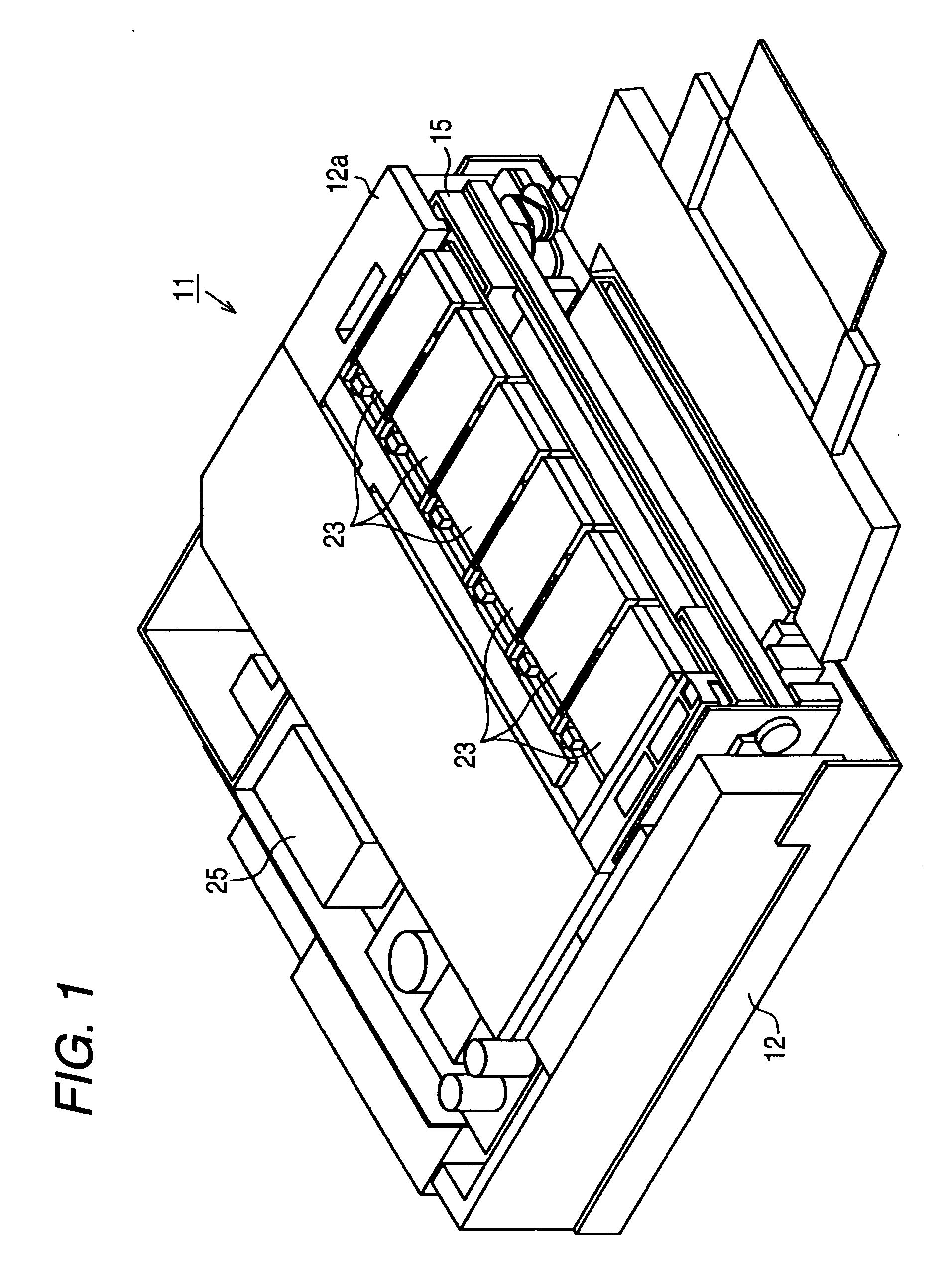
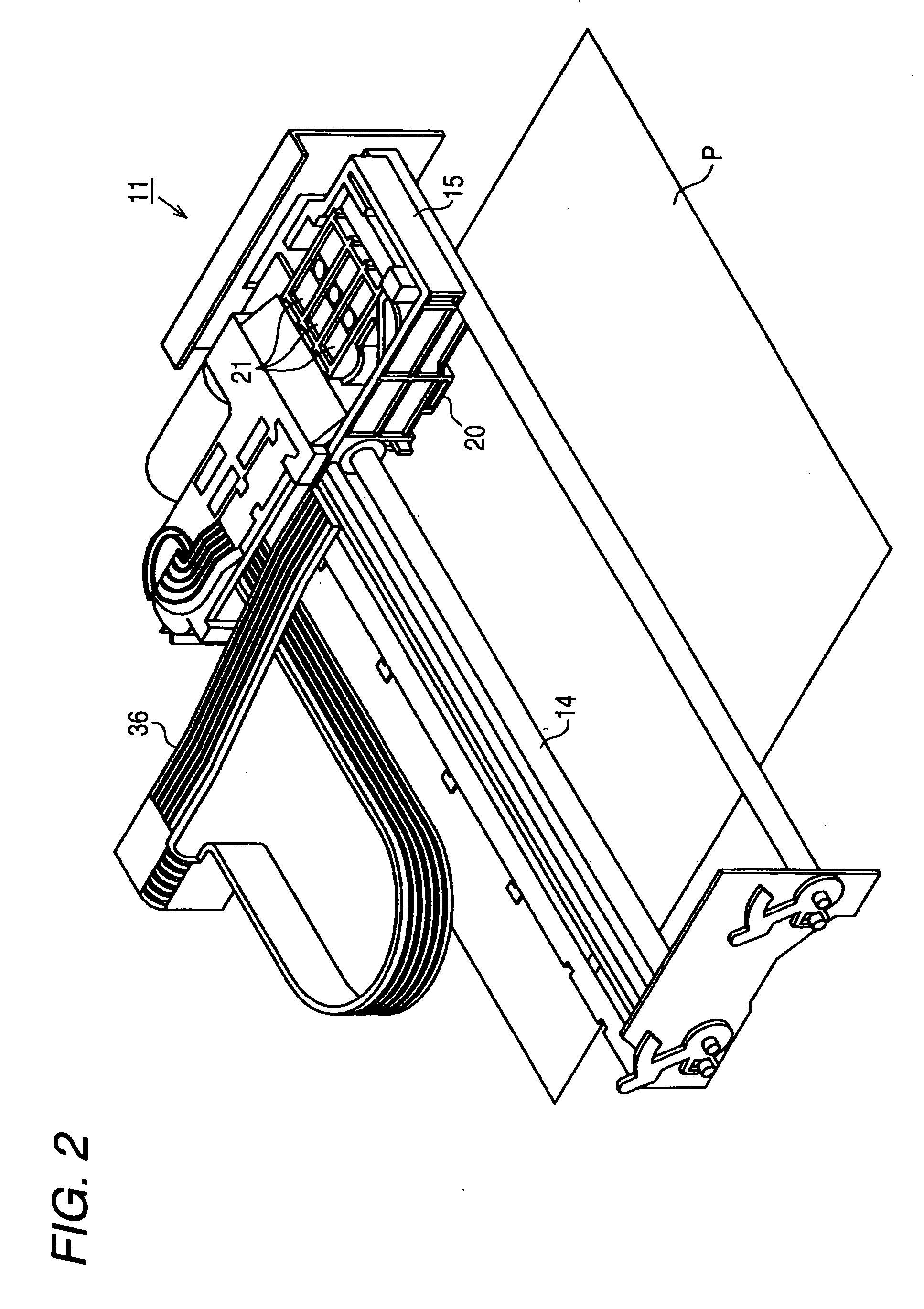
[0052]FIG. 1 is a perspective view to illustrate an outline of a printer of this embodiment. FIG. 2 is a perspective view to illustrate an internal configuration of the printer of this embodiment. FIG. 3 is a schematic diagram to illustrate ink supply of this embodiment.

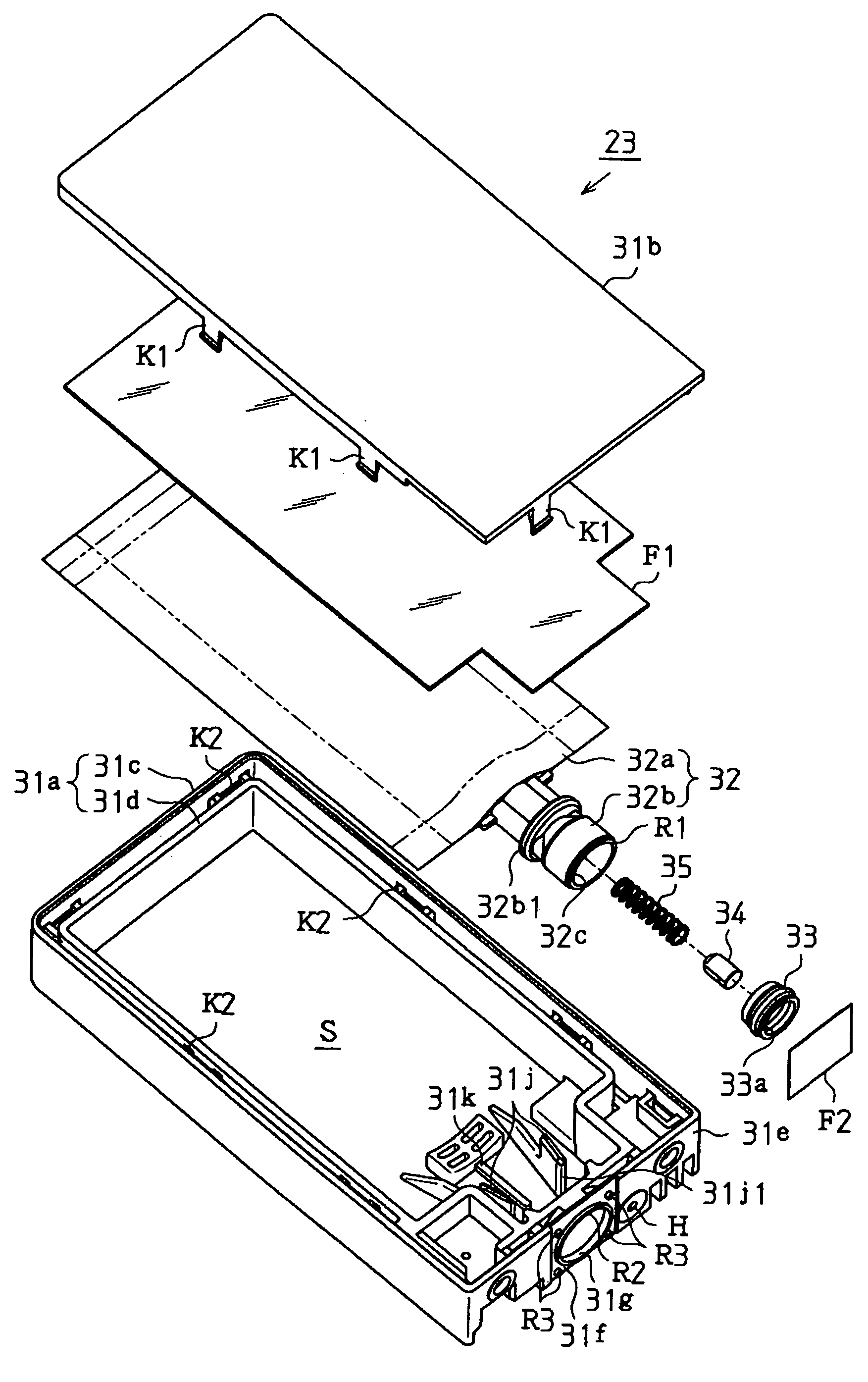
[0053] As shown in FIG. 1, the printer 11, serving as the liquid ejecting apparatus, of this embodiment has a frame 12. And, as shown in FIG. 2, the frame 12 has therein a guide shaft 14, a carriage 15, a recording head 20 serving as the liquid ejecting head, valve units 21, ink cartridges 23 (see FIG. 1) serving as the liquid containers, a pressure pump 25 (see FIG. 1).

[0054] As shown in FIG. 1, the frame 12 is a substantially rectangular-shaped box, at the front of which a cartridge holder 12a is formed.

[0055] As shown in FIG. 2, the guide shaft 14, formed as a rod, is disposed in the fram...


PUM


Abstract

A second sealing film F2 is thermally bonded onto a leading end portion R1 of an ink lead-out member 32b of an ink pack and an annular projecting portion R2 provided on an ink casing 31. Thereby, a gap D produced between the ink lead-out member 32b and the ink casing 31 can be closed from outside the ink casing 31. Accordingly, the airtightness of a space S in the ink casing 31 is kept, thus making it possible to raise the pressure in the space S and generate such a force as to crush the ink pack.

Description

BACKGROUND OF THE INVENTION [0001] The present invention relates to a liquid container. [0002] As a liquid ejecting apparatus that ejects ink droplets through nozzles of a liquid ejecting head, there is an ink jet printer. A liquid container (ink cartridge) storing a liquid (ink) to be supplied to the liquid ejecting head (print head) is detachably mounted in this inkjet printer. The ink cartridge is made up of a casing and members (e.g., a porous member, an ink containing bag, and a film valve) for holding the ink in the casing. To easily house such members in the casing, the casing normally comprises a body casing and a lid portion. [0003] JP-A-5-16377 discloses an ink cartridge having a bag-like ink pack housed in a casing made up of a body casing and a lid portion. This lid portion is provided with a pair of horns and a pair of claw portions. At the same time, the body casing is provided with hole portions corresponding to the horns and recessed portions corresponding to the cla...

Claims


Application Information

Patent Timeline
Patent Type & Authority Applications(United States)
IPC IPC(8): B41J2/175
CPCB41J2002/17516B41J2/17513
Inventor ISHIZAWA, TAKUSEINO, TAKEOKIMURA, HITOTOSHI
Owner SEIKO EPSON CORP
Why Eureka
Try Eureka