Wobble signal demodulation circuit and optical disk apparatus

Inactive Publication Date: 2005-03-24
RICOH KK
View PDF5 Cites 5 Cited by
  • Summary
  • Abstract
  • Description
  • Claims
  • Application Information

AI Technical Summary

Benefits of technology

[0007] The present invention is made in view of the situation noted above and has its first object of providing a wobble signal demodulating circuit that can phase-demodulate the wobble signal with high precision.
[0010] With this, the wobble signal acquired based on the reflection light from the recording surface of the optical disk is processed by the bandpass filter having the central frequency near the fundamental frequency of the carrier part, and the signal of the carrier part is extracted. Further, the clock signal is produced by the signal generation circuit from the carrier part extracted by the bandpass filter, and the phase modulation wave part is subjected to the phase demodulation by the modulation wave demodulation circuit in synchronization with this clock signal. Here, it should be noted that the central frequency of the bandpass filter is adjusted by the frequency adjustment circuit based on the frequency adjustment signal corresponding to the linear velocity of the rotating optical disk, and thus, it becomes possible to prevent the deterioration of output signal of the bandpass filter even when the linear velocity of the rotating optical disk is increased and the fundamental frequency is increased. Thereby, it becomes possible to extract the carrier wave component contained in the wobble signal with high precision. Thus, the precision of the clock signal is improved, and as a result, it becomes possible to phase-demodulate the wobble signal with high precision.
[0012] With this, the wobble signal acquired based on the reflection light from the recording surface of the optical disk is processed by the bandpass filter having the central frequency in the vicinity of the fundamental frequency of the carrier wave part and the signal of the carrier wave part is extracted. Thereby, the first clock signal is produced by the first signal generation circuit from the carrier wave part extracted by the bandpass filter, and the phase modulation wave part is subjected to phase-demodulation by the modulation wave demodulation circuit in synchronization with the first clock signal. Here, it should be noted that the central frequency of the bandpass filter is adjusted by the frequency adjustment circuit based on the frequency adjustment signal corresponding to the linear velocity of the rotating optical disk, and thus, it becomes possible to prevent the deterioration of the output signal of the bandpass filter even in the case the linear velocity of the rotating optical disk is increased and the fundamental frequency is increased. Thereby, it becomes possible to extract the carrier wave component contained in the wobble signal with high precision. Thus, the precision of the first clock signal is improved and as a result, it becomes possible to phase-demodulate the wobble signal with high precision. Further, because the frequency of the first clock signal is adjusted by determining the deviation of phase of the first clock signal and the wobble signal based on the result of the respective phase demodulations obtained by using the first and second clock signals of the same frequency but different phases and because the frequency of the first clock signal is adjusted so as to eliminate or decrease this deviation, the phase deviation of the clock signal (first clock signal) used for the phase demodulation is adjusted, and it becomes possible to phase-demodulate the wobble signal with high precision also with this respect.
[0014] With this, the carrier wave component contained in the wobble signal is extracted with high precision based on the frequency adjustment signal created by the frequency adjustment creation means, and thus, the precision of demodulation of the phase demodulation part of the wobble signal is improved. Thus, it becomes possible to acquire the positional information from the predetermined information contained in the phase modulation wave part of the wobble signal with high precision. Thereby, the recording start position is determined with high precision by the data recording means, and as a result, it becomes possible to carry out high quality recording.

Problems solved by technology

Because of this, there tends to appear a variation in the frequency response characteristics of the filter, while this leads to the problem of variation of quality of the signal thus phase-modulated.
Thereby, it is expected that there would be caused a problem, associated with the variation in the quality of the signal thus phase demodulated, in that the correct address information may not be acquired.
When this occurs, there arises a problem of degradation of recording quality.

Method used


Image

  • Wobble signal demodulation circuit and optical disk apparatus
  • Wobble signal demodulation circuit and optical disk apparatus
  • Wobble signal demodulation circuit and optical disk apparatus

Examples


Embodiment Construction

[0040] Hereinafter, an embodiment of the present invention will be explained with reference to the drawings.

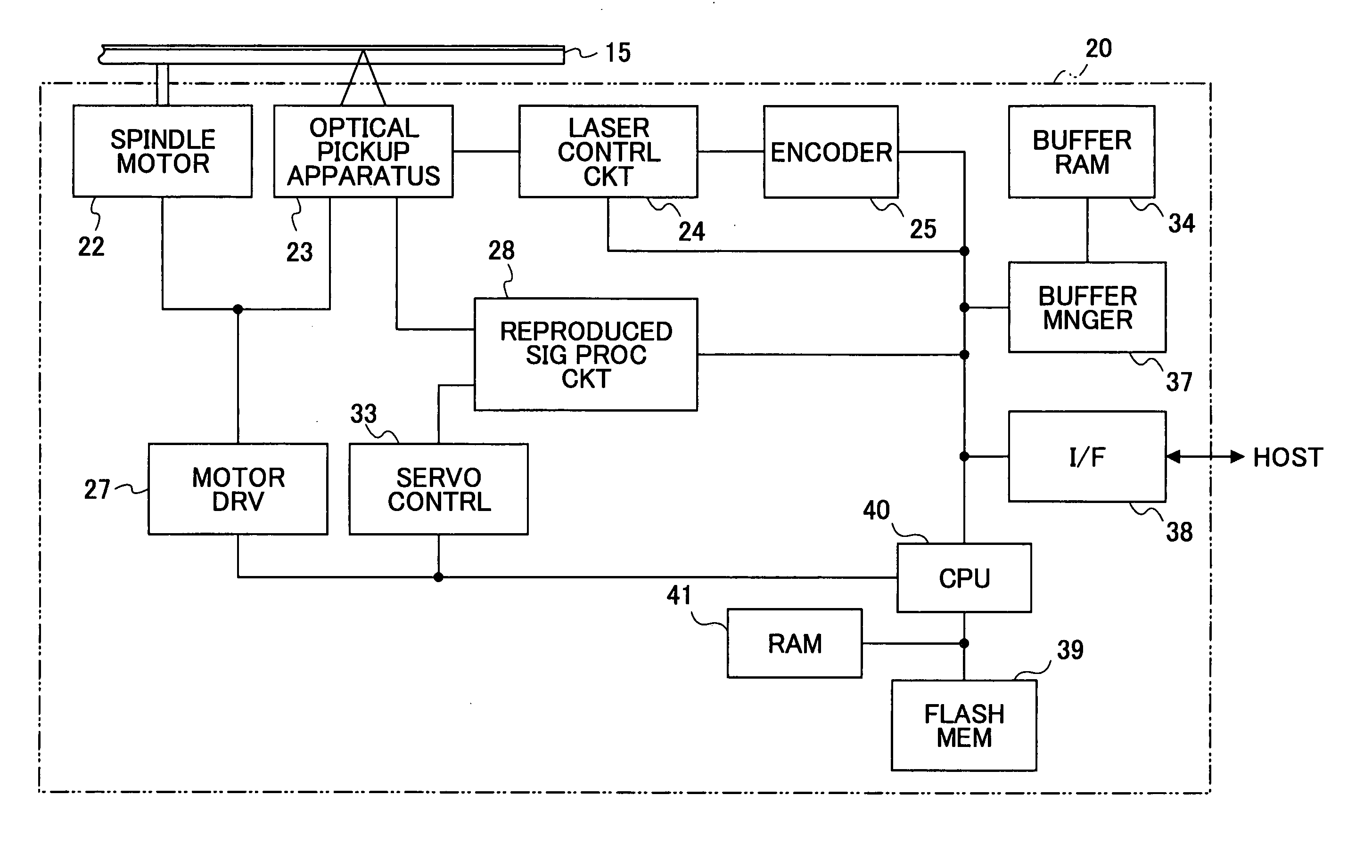
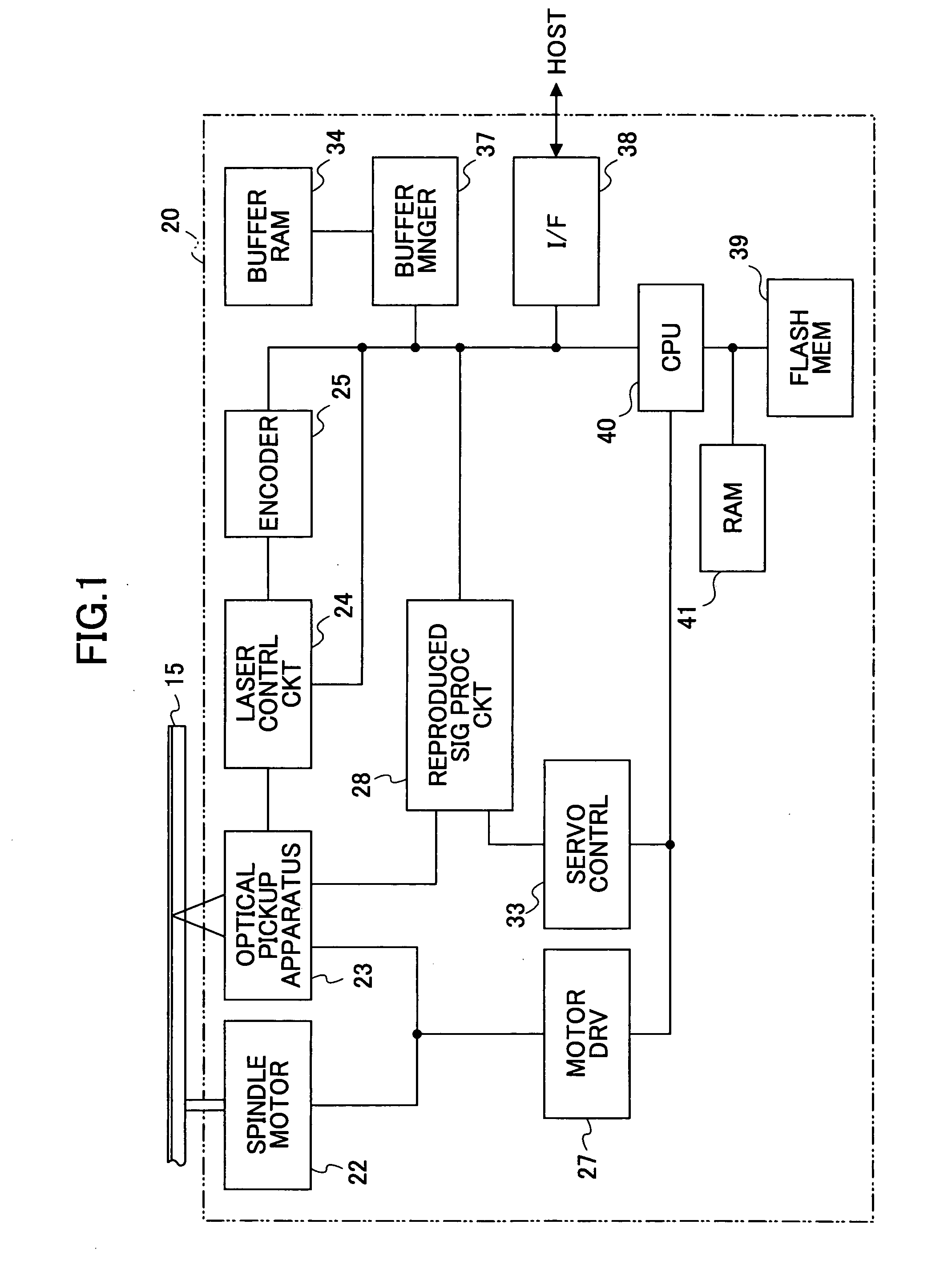
[0041]FIG. 1 shows the outline construction of an optical disk apparatus according to an embodiment of the present invention.

[0042] An optical disk apparatus 20 shown in FIG. 1 comprises: a spindle motor 22 driving an optical disk 15 for causing rotation thereof, an optical pickup apparatus 23, a laser control circuit 24, an encoder 25, a motor driver 27, a reproduced signal processing circuit 28, a servo controller 33, a buffer RAM 34, a buffer manager 37, an interface 38, a flash memory 39, a CPU 40, a RAM 41, and the like. In FIG. 1, it should b e noted that the connection lines show the flow of representative signals and information, but not intended to represent all the connections of the blocks. In the explanation hereinafter, it is assumed that the present embodiment uses the information recording medium in conformity with the DVD+R standard for the optical disk 15.

[...


PUM


Abstract

A wobble signal demodulation circuit carries out phase demodulation of a wobble signal acquired from a reflection light reflected from a recording surface of an optical disk, the recording surface carrying a meandering track thereon, wherein the wobble signal including a carrier wave part having a predetermined fundamental frequency and a phase modulation wave part added with predetermined information. The wobble signal demodulation circuit includes a bandpass filter having a central frequency in the vicinity of the fundamental frequency, the bandpass filter extracting a signal of the carrier wave part from said wobble signal; a frequency adjustment circuit that adjusts the central frequency of the bandpass filter based on a frequency adjustment signal corresponding to a linear velocity of the optical disk under rotation; a signal generation circuit that produces a clock signal from the extracted signal of the carrier wave part; and a modulation-wave demodulation circuit that carries out phase demodulation for the phase demodulation part of the wobble signal in synchronization with the clock signal.

Description

CROSS REFERENCE TO RELATED APPLICATIONS [0001] The present invention is based on the PCT priority application PCT / JP2004 / 063399 filed on Mar. 15, 2004 and the Japanese priority applications 2003-309889 and 2003-348378 respectively filed on Sep. 2, 2003 and Oct. 7, 2003, the entire contents of which are incorporated herein as reference.BACKGROUND OF THE INVENTION [0002] The present invention relates to wobble signal demodulation circuit and optical disk apparatus and in more detail to a wobble signal demodulation circuit that performs phase demodulation of a wobble signal obtained from an optical disk and an optical disk apparatus having such a wobble signal demodulation circuit. [0003] With progress in the digital technology and improvement in the data compression technology, optical disks such as CD (Compact Disc) or DVD (Digital Versatile Disc), which is an optical disk capable of recording data of seven times as large as the data amount recorded in a disk body of the same diamete...

Claims


Application Information

Patent Timeline
IPC IPC(8): G11B3/00G11B7/0045G11B7/005G11B20/14
CPCG11B7/0053G11B19/28G11B7/24082
Inventor SUGATA, KOHICHIROH
Owner RICOH KK
Why Eureka
Try Eureka