Flexible panel

a technology of flexible panels and panels, applied in the field of flexible panels, can solve problems such as the path to separation, and achieve the effects of reducing the shear stress on the cord, easy assembly, and convenient manufactur

Inactive Publication Date: 2005-03-24
THORNE MICHAEL B
View PDF16 Cites 29 Cited by
  • Summary
  • Abstract
  • Description
  • Claims
  • Application Information

AI Technical Summary

Benefits of technology

[0020] The notches on a same bar are symmetrical to each other with a first notch in the top surface on one side of the bar, and a second notch in the bottom surface on the other side of the bar. Because of this symmetry, the bars are easily manufactured and the panel made with these bars is easily assembled without distinction as to the orientation of the top and bottom surfaces of the bars. In use, a load applied to one bar is distributed to the other bars in an upstair direction relative to the shiplap joints.
[0021] In another aspect of the present invention, each hole has an axis that is contiguous with the overlapping horizontal surfaces of the notches. Each hole along the shiplap joint is made of two separable cylindrical grooves facing each other and forming a closed cylindrical wall when the shiplap joint is integral. These grooves jointly define a separable cylindrical segment when the shiplap joint is pulled apart. This separable segment provides the spacer means to allow the elastic cord to bend and stretch when the shiplap joint is separated to reduce the shear stress on the cord.
[0022] In yet another aspect of the present invention, there is provided a shower mat kit comprising in combination the flexible panel having shiplap joints between the bars thereof, and a bag having a mesh-like fabric on its bottom surface. The flexible panel is usable as a shower mat. In this aspect of the present invention, the bag contains the flexible panel in a rolled-up cylindrical shape. In this configuration, the bending of the shiplap joints causes one corner on every bar to project outwardly from the cylindrical shape, and causes the inside surface of the bag to stretch away from the outside surface of the bars, thereby creating aeration channels along the outside surfaces of the bars to facilitate the drying of the flexible panel when the panel is wet.

Problems solved by technology

However, when a concentrated load is placed or moved on such a flexible pathway, the relative movements of adjacent bars tend to shear the cables holding the bars together.
It is believed that these shear stresses on the cables eventually break the cables and cause the pathway to separate.

Method used


Image

  • Flexible panel
  • Flexible panel
  • Flexible panel

Examples


Embodiment Construction

[0039] While this invention is susceptible of embodiment in many different forms, there are shown in the drawings and will be described in details herein three specific embodiments, with the understanding that the present disclosure is to be considered as an example of the principles of the invention and is not intended to limit the invention to the embodiments illustrated and described.

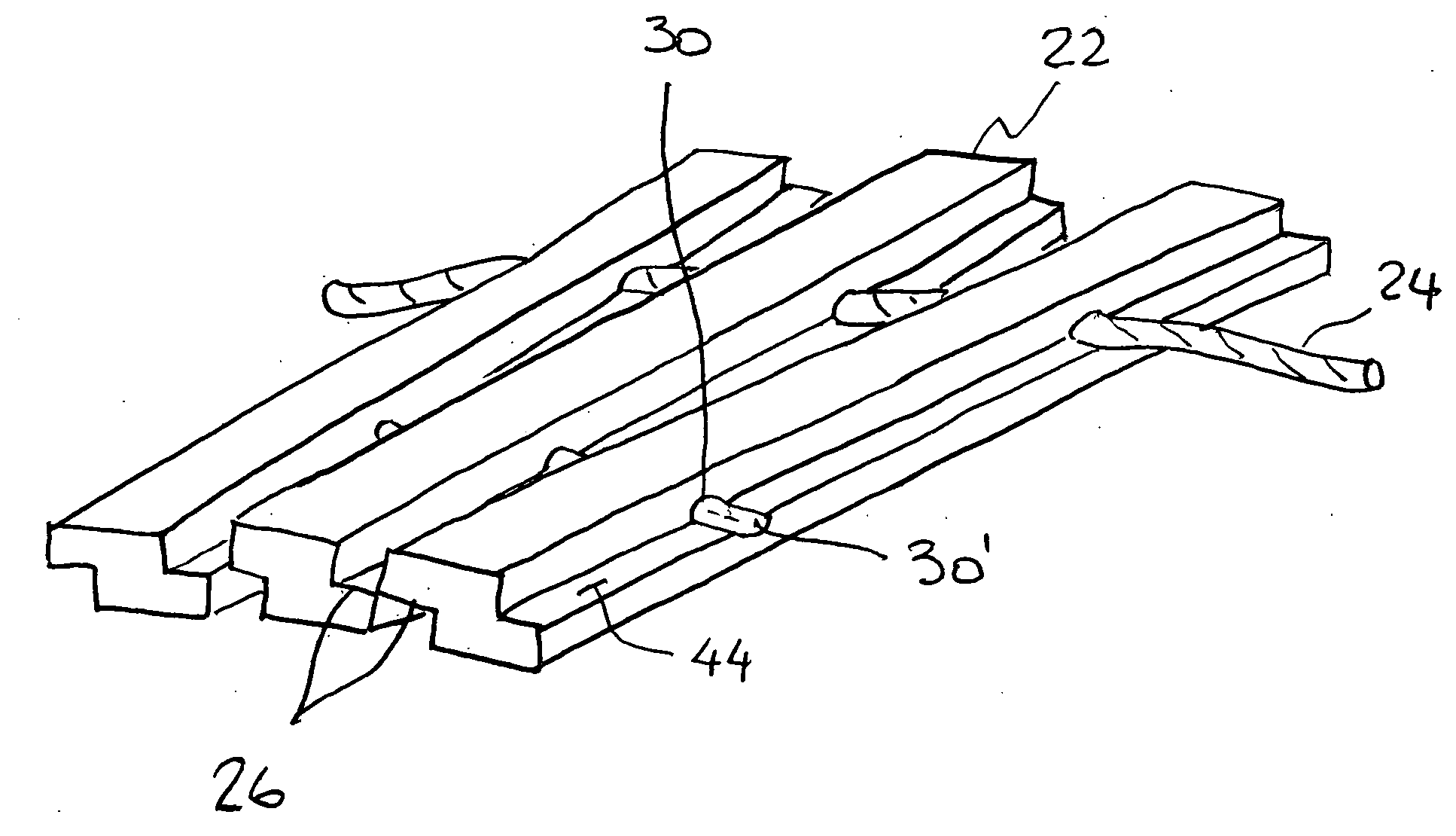
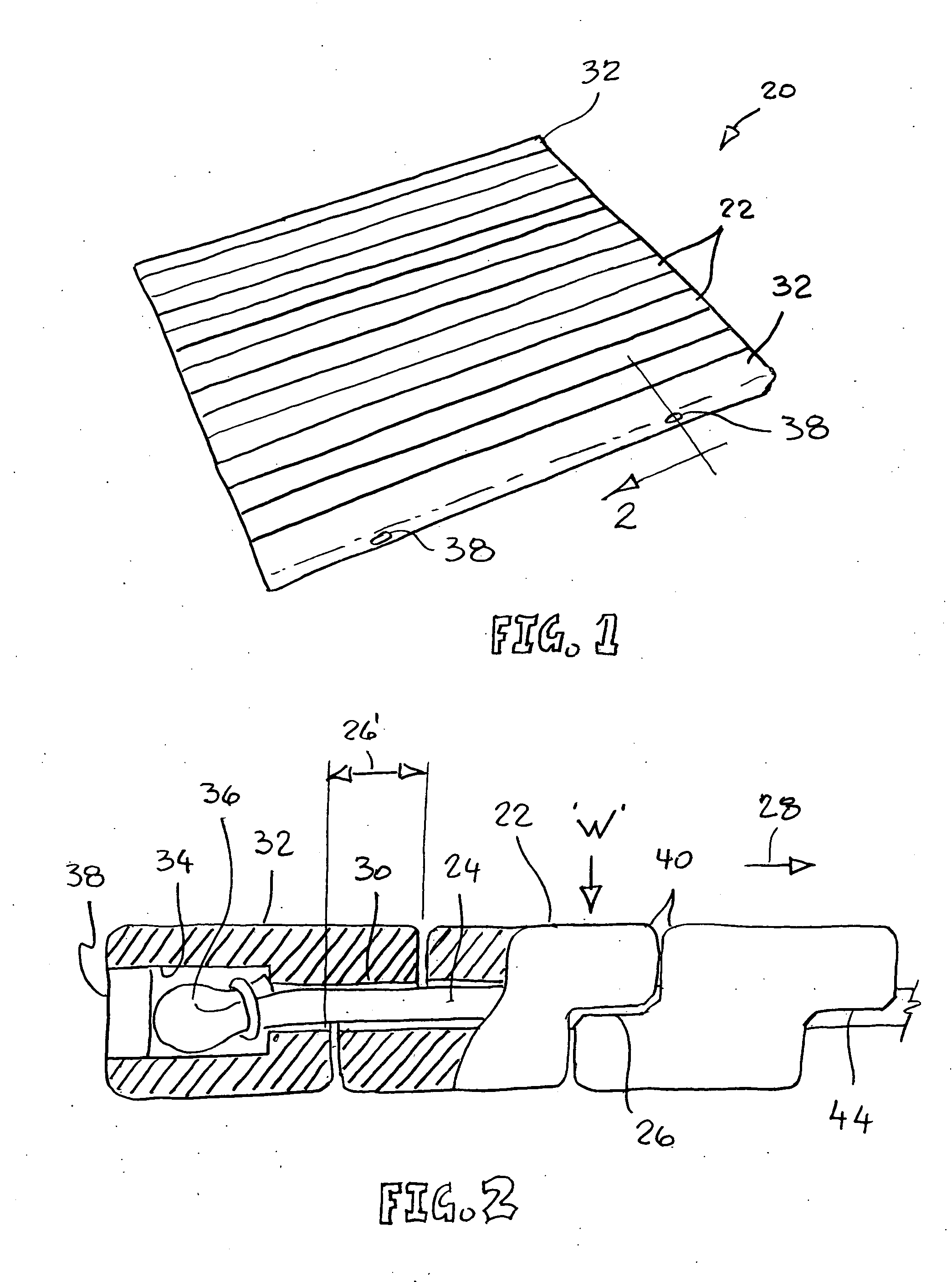
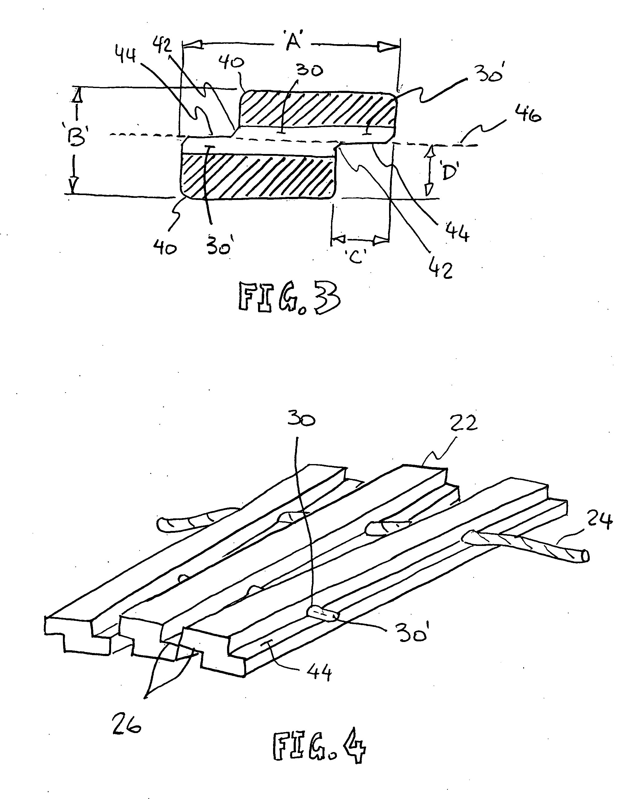
[0040] In a first preferred embodiment of the present invention, there is provided a panel 20 made of juxtaposed rigid bars 22, as illustrated in FIG. 1, through which are threaded two elastic cords. These elastic cords 24 are better illustrated in FIGS. 2 and 4. Each panel 20 is rigid along the bars 22 and is flexible across the bars. The bars 22 have shiplap edges 26 as shown in FIGS. 2 and 4 such that the edge of one bar overlaps the edge of an adjacent bar to distribute a concentrated load to a number of bars. The bars 22 in the panel 20 are held together by the tension set in the elastic cords ...


PUM

PropertyMeasurementUnit
flexibleaaaaaaaaaa
thicknessaaaaaaaaaa
depth dimensionaaaaaaaaaa

Abstract

The flexible panel is made of juxtaposed rectangular bars each having holes extending transversely therein and elastic cords threaded through these holes for keeping the bars closely positioned side-by-side. Adjacent bars have a shiplap joint there between comprising a first notch in the top surface and the first side surface of a first bar, and a second notch in the bottom surface and the second side surface of the second bar, wherein these notches have overlapping horizontal surfaces. In another aspect of the present invention, each hole along the shiplap joint is made of two separable cylindrical grooves facing each other and forming a closed cylindrical wall when the shiplap joint is integral and a separable segment when the shiplap joint is pulled apart.

Description

FIELD OF THE INVENTION [0001] This invention pertains to flexible panels made of juxtaposed rigid bars through which cables are threaded. More particularly, it relates to flexible panels in which the bars have shiplap edges and the cables are elastic cords. BACKGROUND OF THE INVENTION [0002] Flexible walkways and roadways are generally made of parallel bars that are held side by side by flexible tie members. These pathways are used to cover soft grounds, for example, to prevent pedestrian or vehicle traffic from damaging the ground surfaces. In many applications, the pathways are made of rectangular or tubular bars that are held together by cables passing transversely through the bars. However, when a concentrated load is placed or moved on such a flexible pathway, the relative movements of adjacent bars tend to shear the cables holding the bars together. It is believed that these shear stresses on the cables eventually break the cables and cause the pathway to separate. [0003] Exam...

Claims


Application Information

Patent Timeline
Patent Type & Authority Applications(United States)
IPC IPC(8): A47K3/00B65G69/28E01C5/00E01C9/08E01D15/133E01D15/20
CPCE01C9/086A47K3/002
Inventor THORNE, MICHAEL B.
Owner THORNE MICHAEL B
Why Eureka
Try Eureka