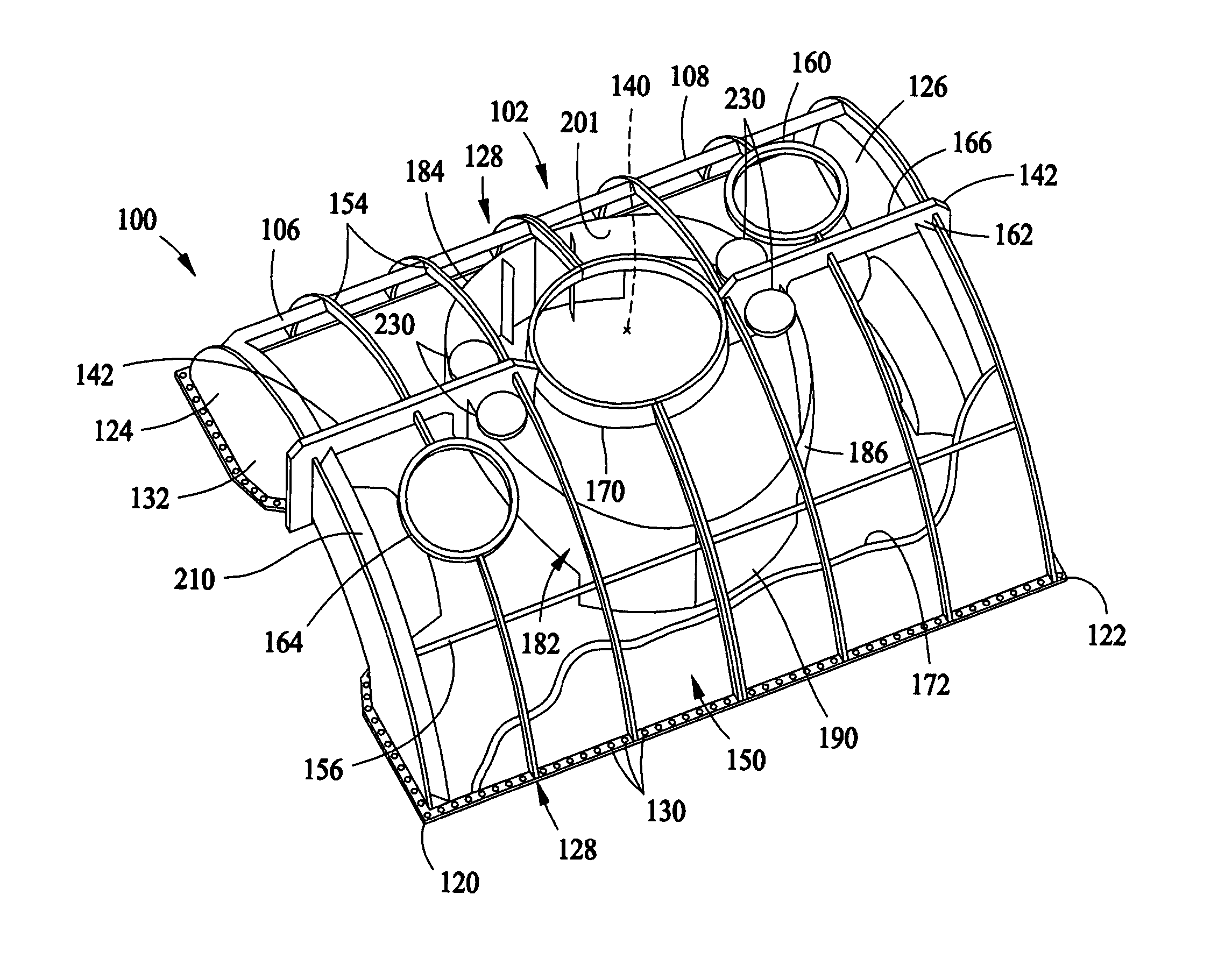
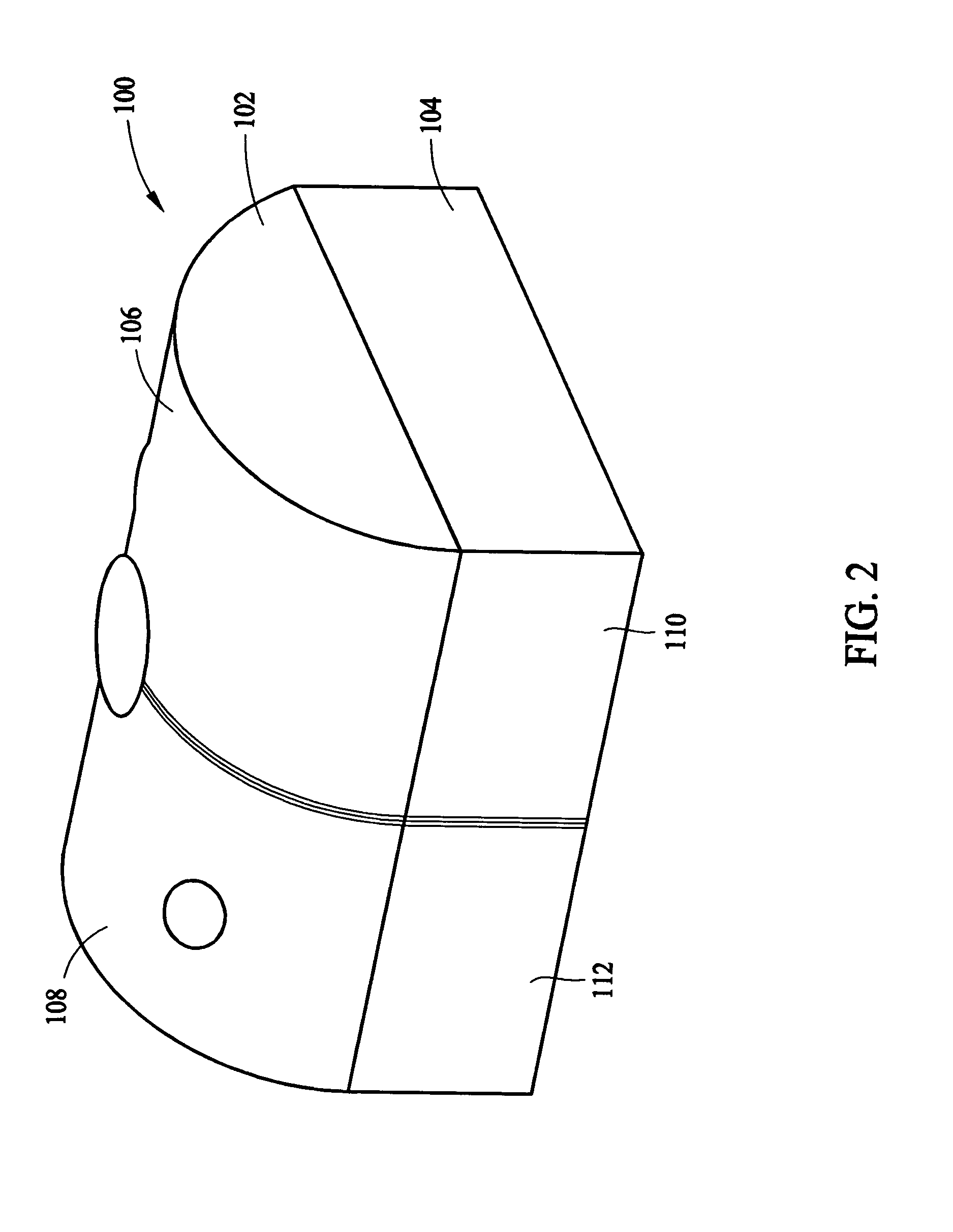
Low pressure steam turbine exhaust hood
a steam turbine and low pressure technology, applied in the field of steam turbines, can solve problems such as reducing the efficiency of the exhaust hood, and achieve the effect of facilitating reducing the loss of flow separation
- Summary
- Abstract
- Description
- Claims
- Application Information
AI Technical Summary
Benefits of technology
Problems solved by technology
Method used
Image

Examples
Embodiment Construction
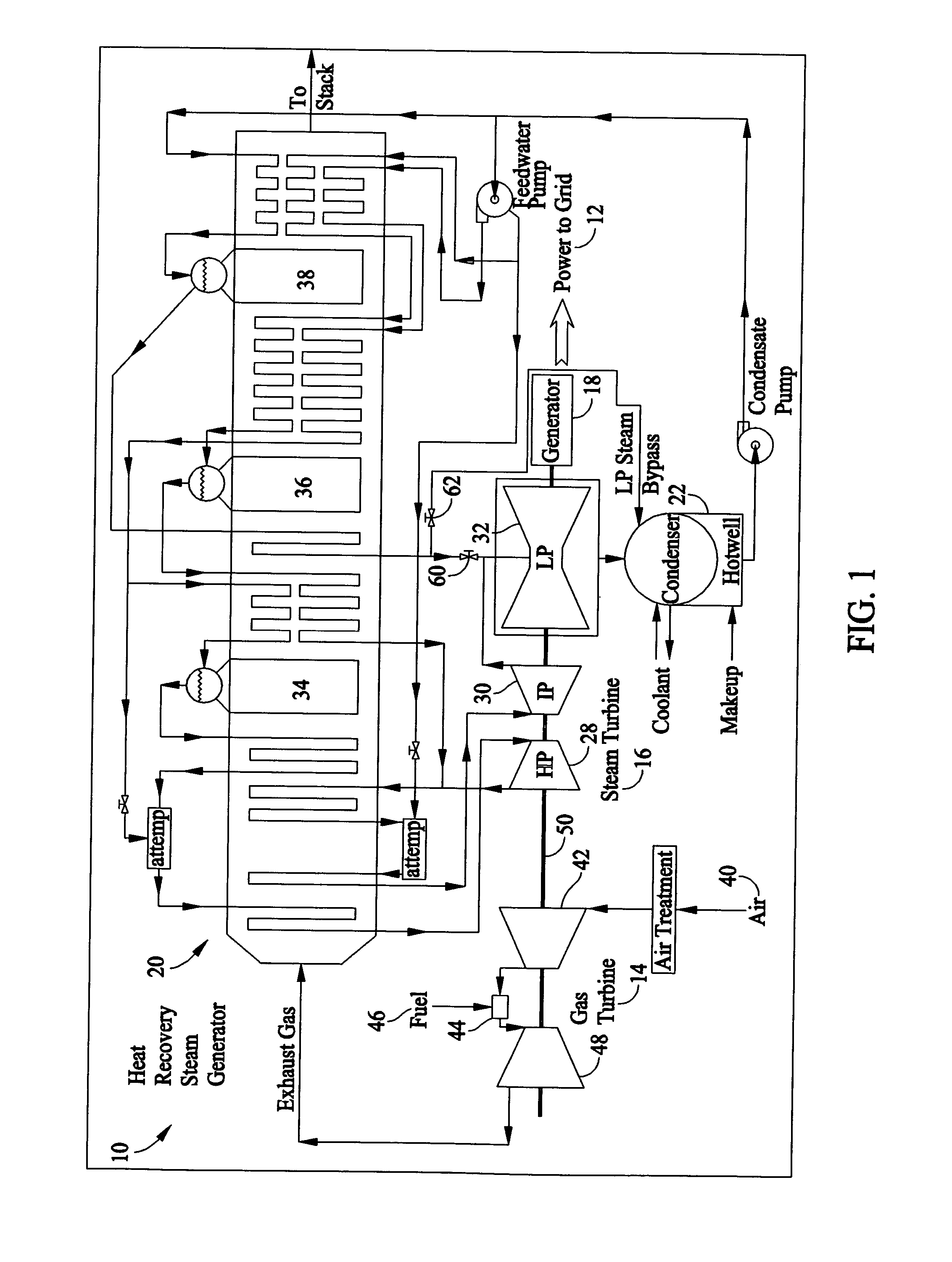
[0013]FIG. 1 is a schematic illustration of an exemplary power plant 10 configured to supply energy to a power grid 12. In the exemplary embodiment, power plant 10 is a multi-pressure, single-shaft combined cycle power plant 10 and includes a gas turbine 14 that may or may not be coupled to a steam turbine assembly 16, and a common generator 18 via a shaft 50. Power plant 10 also includes a heat recovery steam generator (HRSG) 20, a condenser 22, and a plurality of pumps (not shown) that repressurize the condensate supplied to HRSG 20. In the exemplary embodiment, steam turbine assembly 16 includes a High Pressure (HP) turbine section 28, an Intermediate Pressure (IP) turbine section 30, and a Low Pressure (LP) turbine section 32, and HRSG 20 includes a high pressure section 34, an intermediate pressure section 36, and a low pressure section 38. In another embodiment, power plant 10 is a multi-pressure, multi-shaft combined cycle power plant 10, wherein gas turbine 14 is coupled to ...
PUM
| Property | Measurement | Unit |
|---|---|---|
| axis of symmetry | aaaaa | aaaaa |
| distance | aaaaa | aaaaa |
| symmetry | aaaaa | aaaaa |
Abstract
Description
Claims
Application Information