Connecting structure for a striking plate of a golf club head

Inactive Publication Date: 2005-03-24
NELSON PRECISION CASTING
View PDF8 Cites 17 Cited by
  • Summary
  • Abstract
  • Description
  • Claims
  • Application Information

AI Technical Summary

Benefits of technology

[0006] An object of the present invention is to provide a connecting structure for a striking plate of a golf club head that reduces the amount of the striking stress of the s

Problems solved by technology

However, when the golf club head body 10 is made of a material having a greater Young's modulus (e.g., stainless steel or carbon steel having a Young's modulus of 3×10⁷ psi) under the consideration of overall structural strength, the golf club head body 10 having

Method used


Image

  • Connecting structure for a striking plate of a golf club head
  • Connecting structure for a striking plate of a golf club head
  • Connecting structure for a striking plate of a golf club head

Examples


Embodiment Construction

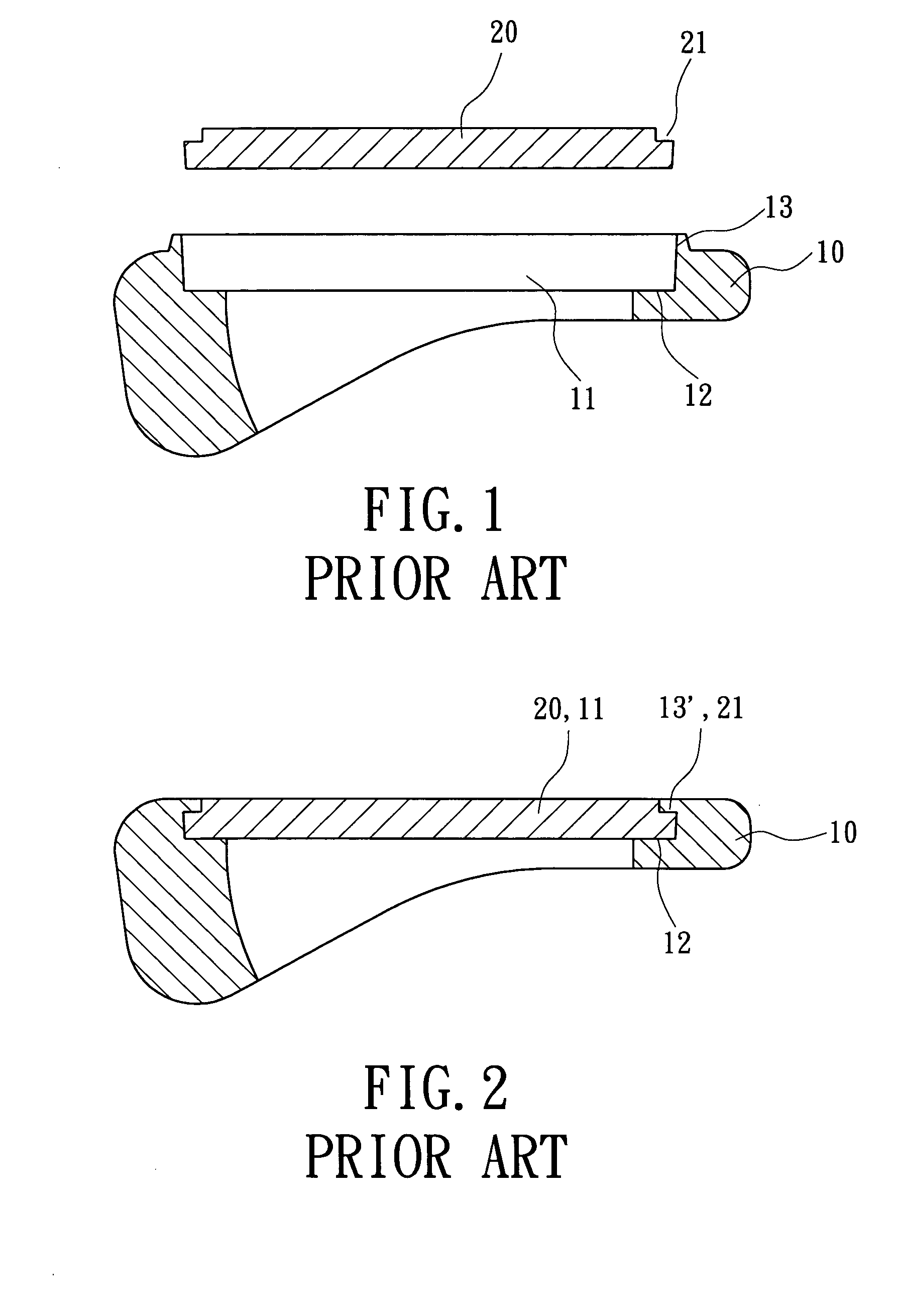
[0026] Preferred embodiments of the present invention are now to be described hereinafter in detail, in which the same reference numerals are used in the preferred embodiments for the same parts as those in the prior art to avoid redundant description.

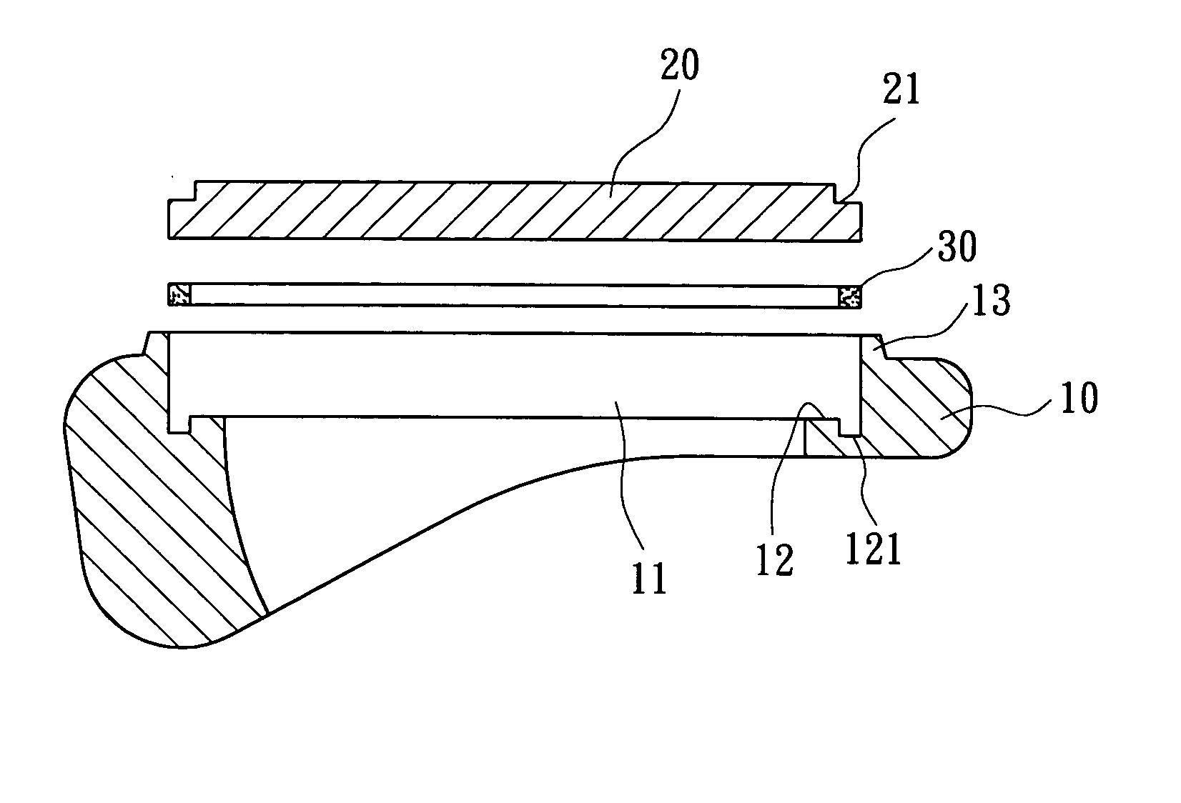
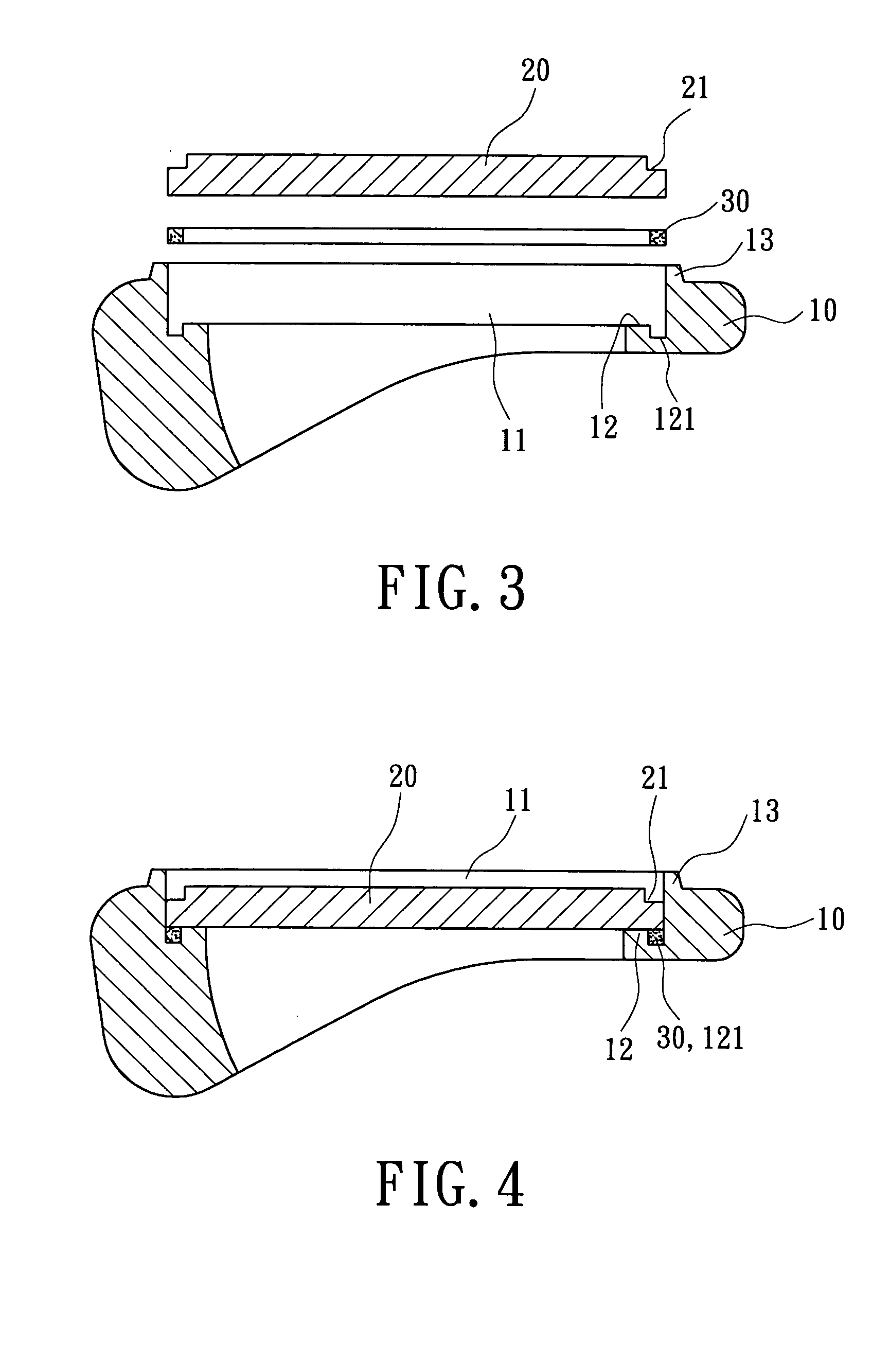
[0027]FIG. 3 is an exploded sectional view illustrating a golf club head in accordance with the present invention before processing. FIG. 4 is a sectional view of the golf club head in FIG. 3. FIG. 5 is a sectional view of the golf club head in accordance with the present invention after processing. FIG. 6 is an enlarged view of a circled portion in FIG. 5.

[0028] Referring to FIG. 3, the golf club head in accordance with the present invention includes a golf club head body 10, a striking plate 20, and a ring 30. The golf club head body 10 is made of a material having a Young's modulus greater than 3×10⁷ psi, such as stainless steel, carbon steel, alloy steel, or Fe—Mn—Al alloy. The golf club head body 10 includes a recession 11 in a ...


PUM


Abstract

A golf club head includes a golf club head body, a ring, and a striking plate. The golf club head body includes a recession in a side thereof, the recession including a shoulder on an inner peripheral edge thereof. The ring is mounted on the shoulder of the golf club head body. The striking plate is mounted in the recession of the golf club head body and securely engaged with the ring, with the ring supporting a rear side of the striking plate. The striking plate and the golf club head body have a relatively small contact area therebetween to thereby reduce an amount of the striking stress of the striking plate absorbed by the golf club head body, thereby assuring high deformability of the striking plate.

Description

BACKGROUND OF THE INVENTION [0001] 1. Field of the Invention [0002] The present invention relates to a connecting structure for connecting a striking plate of a golf club head. In particular, the present invention relates to a connecting structure for connecting a striking plate to a golf club head body. [0003] 2. Description of Related Art [0004]FIGS. 1 and 2 of the drawings illustrate a typical golf club head including a golf club head body 10 and a striking plate 20. The golf club head body 10 includes a recession 11, with a shoulder 12 being formed on an inner peripheral edge of the recession 11 and with a flange 13 being formed on an outer peripheral edge of the recession 11. The striking plate 20 includes a stepped portion 21 on a periphery thereof. When connecting the striking plate 20 to the golf club head body 10, the striking plate 20 is firstly inserted into the recession 11, and a pressing block (not shown) is used to press the flange 13, causing the flange 13 to deform ...

Claims


Application Information

Patent Timeline
IPC IPC(8): A63B53/04A63B59/00
CPCA63B53/04A63B53/047A63B2209/00A63B2053/0416A63B59/0092A63B60/54A63B53/0416A63B60/00
Inventor CHEN, CHAN-TUNGHOU, WEN-CHING
Owner NELSON PRECISION CASTING
Why Eureka
Try Eureka