Splint combined use cast absence for bone fracture fixing

Inactive Publication Date: 2005-03-24
KIM KYUNG JIN
View PDF14 Cites 25 Cited by
  • Summary
  • Abstract
  • Description
  • Claims
  • Application Information

AI Technical Summary

Benefits of technology

[0010] An object of the present invention is to provide a combined splint and cast for fixing fractured bones which can fast and easily fix the fractured bones by injection-molding a foot fixing member, a connecting member, and a knee fixing member of various sizes according to body measurements and using the respective members individually or cooperatively according to the use, for example, a short leg splint, a PTB splint or a long leg splint, and reduce the time consumed to apply the cast and decrease the cost for the cast application by combining a splint and a cast into one and omitting the intermediate process of applying the plaster cast.
[0011] Another object of the present invention is to provide a combined splint and cast for fixing fractured bones which can obtain a precise immobilization effect by eliminating difference in cast application skill between surgical operators and assistants, and prevent side effects, such as contamination caused by mold or infectious bacteria on the cast portion by providing a plurality of ventilation holes o

Problems solved by technology

The plaster bandage, however, has a problem in that it has to be wound on the injured body part in sufficient thickness, thereby taking lots of time to be wound.
Inevitably, it gets crumpled on the curved part.
Further, since it is made in a long rectangular form, it fails to closely wrap the injured body part in accordance with the thickness of the curved shape, e.g., the wrist, arm, ankle and calf.
In this case, the splint gets loose from the injured body part and fails to tightly support the injured body part, thereby badly affecting the fractured part.
Furthermore, the method using the plaster bandage has problems in that since the work process is complicated and the plaster bandage is wound over the injured body part, mold or infectious bacteria may grow

Method used


Image

  • Splint combined use cast absence for bone fracture fixing
  • Splint combined use cast absence for bone fracture fixing
  • Splint combined use cast absence for bone fracture fixing

Examples


Embodiment Construction

[0024] The present invention will now be described in detail in connection with preferred embodiments with reference to the accompanying drawings. For reference, like reference characters designate corresponding parts throughout several views.

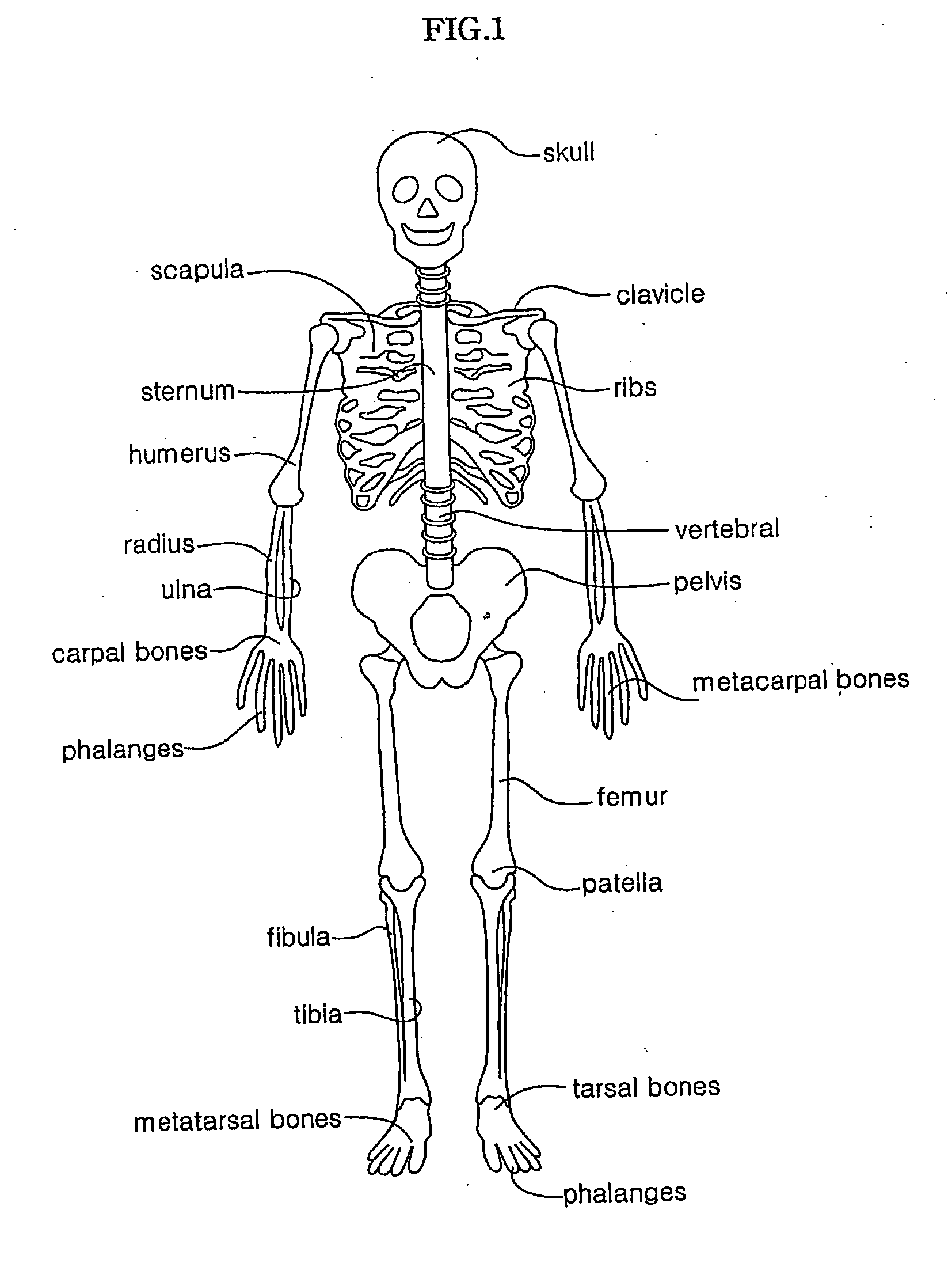
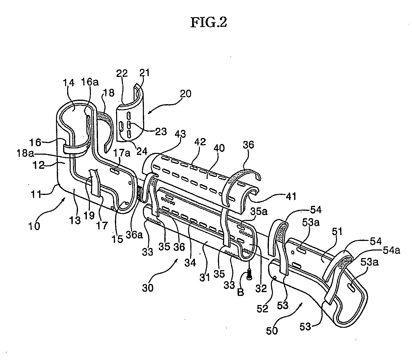
[0025]FIG. 1 is a front view illustrating the human skeletal system, and FIG. 2 is an exploded perspective view of a combined splint and cast according to the present invention.

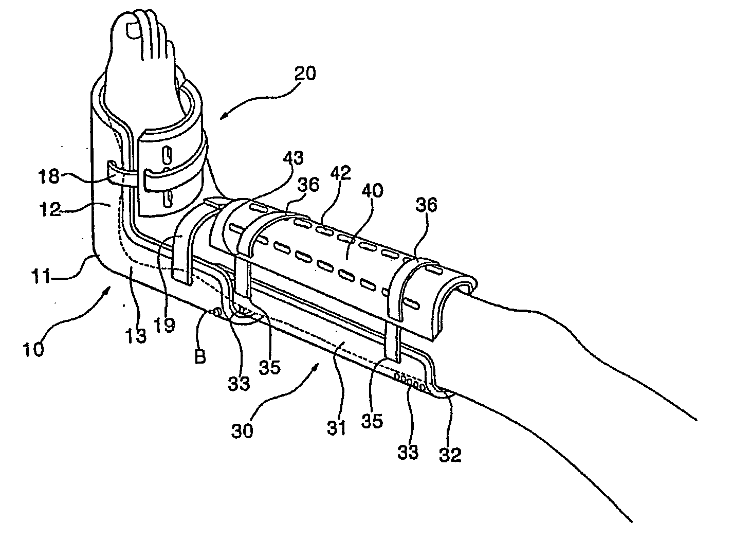
[0026] Referring to FIGS. 1 and 2, the combined splint and cast is used when fracture occurs in the leg. Since leg bones bear the body weight, if one person has a fractured leg, he or she is difficult to walk and needs crutches or a walking stick. In this case, surgical operation is carried out after selecting the methods for fixing and reducing the fractured bones. The combined splint and cast used t each portion includes a foot fixing member 10 having the upper and lower foot fixing members 20 and 11 for immobilizing the region from the metatarsophalangeal (MP) joint...


PUM


Abstract

Disclosed is a combined splint and cast for immobilizing the injured body part due to fracture, ligament rupture, dislocation or the like. In particular, the present invention relates to a combined splint and cast for immobilizing fractured bones, in which a splint and a cast used for a predetermined period of time until a swelling in the injured body part subsides are injec-tion-molded to be combined into one. Therefore, the present invention can solve inconvenience of working with the conventional plaster cast member by using a foot fixing member, a connecting member and a knee fixing member of the combined splint and cast individually or cooperatively according to the use, for example, a short leg splint, a Patella Tendon Bearing (PTB) splint or a long leg splint, minimize the sequelae, such as joint contracture by making possible early joint movement, and correct an inaccurate reduction at its initial stage at any time and malunion by making intermediate inspections.

Description

TECHNICAL FIELD [0001] The present invention relates to a combined splint and cast for immobilizing the injured body part due to fracture, ligament rupture, dislocation or the like. In particular, the present invention relates to a combined splint and cast for immobilizing fractured bones, in which a splint and a cast used for a predetermined period of time until a swelling in the injured body part subsides are injection-molded to be combined into one. Therefore, the present invention can solve inconvenience of working with the conventional plaster cast member by using a foot fixing member, a connecting member and a knee fixing member of the combined splint and cast individually or cooperatively according to the use, for example, a short leg splint, a Patella Tendon Bearing(PFB) splint or a long leg splint, minimize the sequelae, such as joint contracture by making possible early joint movement, and frequently check an inaccurate reduction at its initial stage and malunion by making...

Claims


Application Information

Patent Timeline
IPC IPC(8): A61F13/04A61F5/01A61F5/058
CPCA61F5/0585A61F5/058
Inventor KIM, KYUNG-JIN
Owner KIM KYUNG JIN
Why Eureka
Try Eureka