Method and device for suture isolation

Active Publication Date: 2005-03-24
MORRIS JOHN K +1
View PDF25 Cites 80 Cited by
  • Summary
  • Abstract
  • Description
  • Claims
  • Application Information

AI Technical Summary

Benefits of technology

[0020] These and other objects are achieved in the invention herein disclosed which is a method and device for management of sutures within the working cannula through the temporary “parking” of sutures within slots on the exterior portion of the cannula, the slots maintaining tension on, and orientation of, sutures placed therein. In one embodim

Problems solved by technology

This results in decreased opportunities for erro

Method used


Image

  • Method and device for suture isolation
  • Method and device for suture isolation
  • Method and device for suture isolation

Examples


Example

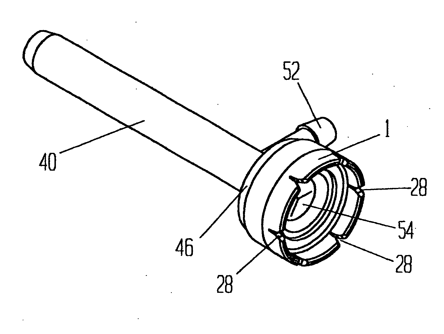
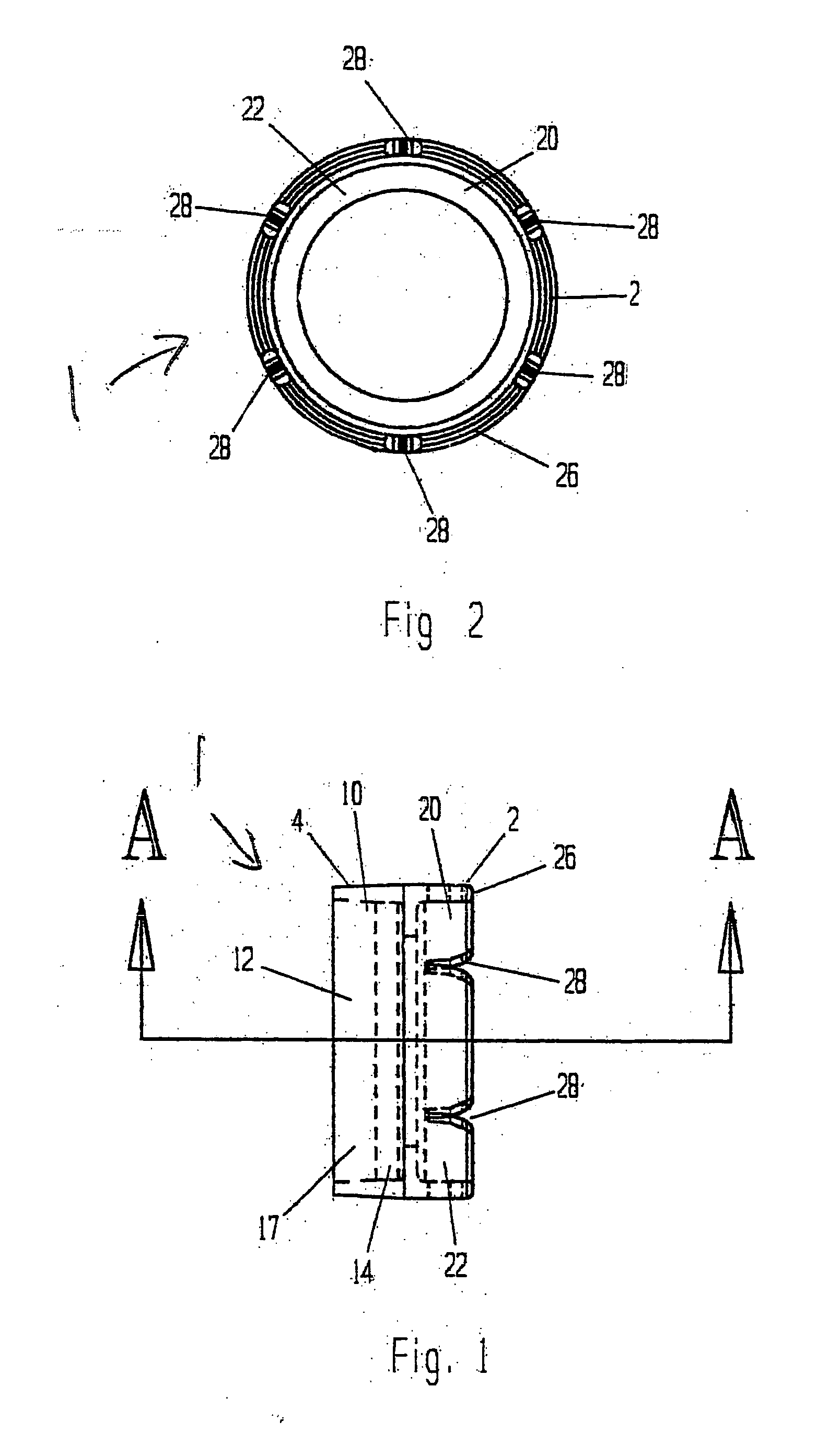
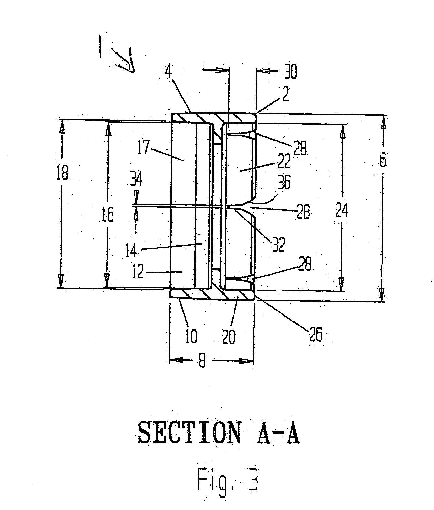
[0050] Referring to FIGS. 1 through 3, suture isolator 1 has a proximal end 2, a distal end 4, outer diameter 6 and length 8. Distal portion 10 has a recess 12 formed therein, recess 12 having a cylindrical portion 14 of diameter 16 and a tapered portion 17 in which the diameter increases to diameter 18. Proximal portion 20 has a cylindrical recess 22 of diameter 24 formed therein so as to produce proximal rim 26. Proximal rim 26 has a plurality of slots 28 of depth 30 having a distal portion 32 of width 34 and a tapered proximal portion 36. Width 34 of distal portion 32 is less than the thickness of the suture generally used for arthroscopic rotator cuff repair so that suture removably placed in slots 28 is held securely. Isolator 1 is made of a rigid metallic or polymeric material.

[0051] Referring to FIGS. 4 through 6, cannula 40 has an elongated tubular distal portion 42 of diameter 44 and a proximal portion 46 of diameter 48, diameter 48 being slightly greater than diameter 16 ...


PUM


Abstract

A method and device provides features for the temporary “parking” of sutures with respect to a cannula. In the preferred embodiments the features are slots that maintain tension on, and orientation of, sutures placed therein. The slots or features may be integral with the cannula or part of a separate device which may be removably affixed to the external portion of a cannula. The invention eliminates the multiple steps inherent in current suture management techniques for arthroscopic procedures, particularly rotator cuff repair and assists in tensioning/advancement of tissue into its repair site.

Description

REFERENCE TO RELATED APPLICATION [0001] This application claims priority from U.S. Provisional Patent Application Ser. No. 60 / 484,243, filed July 2, 2003, the entire content of which is incorporated herein by reference.FIELD OF THE INVENTION [0002] The disclosed invention relates to arthroscopic surgery, and more particularly, to the control of sutures to prevent tangling during arthroscopic procedures including rotator cuff repair, labral repair and other soft tissue apposition. BACKGROUND OF THE INVENTION [0003] The advantages of arthroscopic surgery are significant, however, the procedure has been technically demanding, particularly with respect to rotator cuff repair. The introduction of second-generation anchors with improved holding power and larger eyes which allow sutures to slide easily through them, and clear cannulas which improve visualization, has made the procedure easier. Until recently, however, passing suture through the cuff has been a challenging, multi-step proce...

Claims


Application Information

Patent Timeline
IPC IPC(8): A61B17/04A61B17/06A61B17/34
CPCA61B17/0469A61B2017/0496A61B17/3421A61B17/06061
Inventor MORRIS, JOHN K.VAN WYK, ROBERT A.
Owner MORRIS JOHN K
Why Eureka
Try Eureka