Refrigerant circuit and heat pump type hot water supply apparatus

a heat pump and circuit technology, applied in heat pumps, lighting and heating apparatus, compression machines with several condensers, etc., to achieve the effect of ensuring energy saving

Inactive Publication Date: 2005-03-31
SANYO ELECTRIC CO LTD
View PDF8 Cites 40 Cited by
  • Summary
  • Abstract
  • Description
  • Claims
  • Application Information

AI Technical Summary

Benefits of technology

[0023] According to the above heat pump type hot water supply apparatus, the switching unit such as the electromagnetic valves (20, 28, 42a, 42b) is controlled on the basis of the refrigerant temperature at the outlet port of the water heat exchanger, and thus it can be judged whether the driving of the outdoor heat exchanger is needed or not and whether the outdoor heat exchanger should be bypassed or not. On the basis of the above judgment, the switching operation of the switching unit is controlled, so that the energy saving effect can be surely achieved.

Problems solved by technology

CO2 refrigerant is inferior in the cycle efficiency of cooling operation at a higher outside air temperature as compared with HFC refrigerant, etc., however, this construction improves the cycle efficiency under cooling operation.

Method used


Image

  • Refrigerant circuit and heat pump type hot water supply apparatus
  • Refrigerant circuit and heat pump type hot water supply apparatus
  • Refrigerant circuit and heat pump type hot water supply apparatus

Examples


first embodiment

[0038] [First Embodiment]

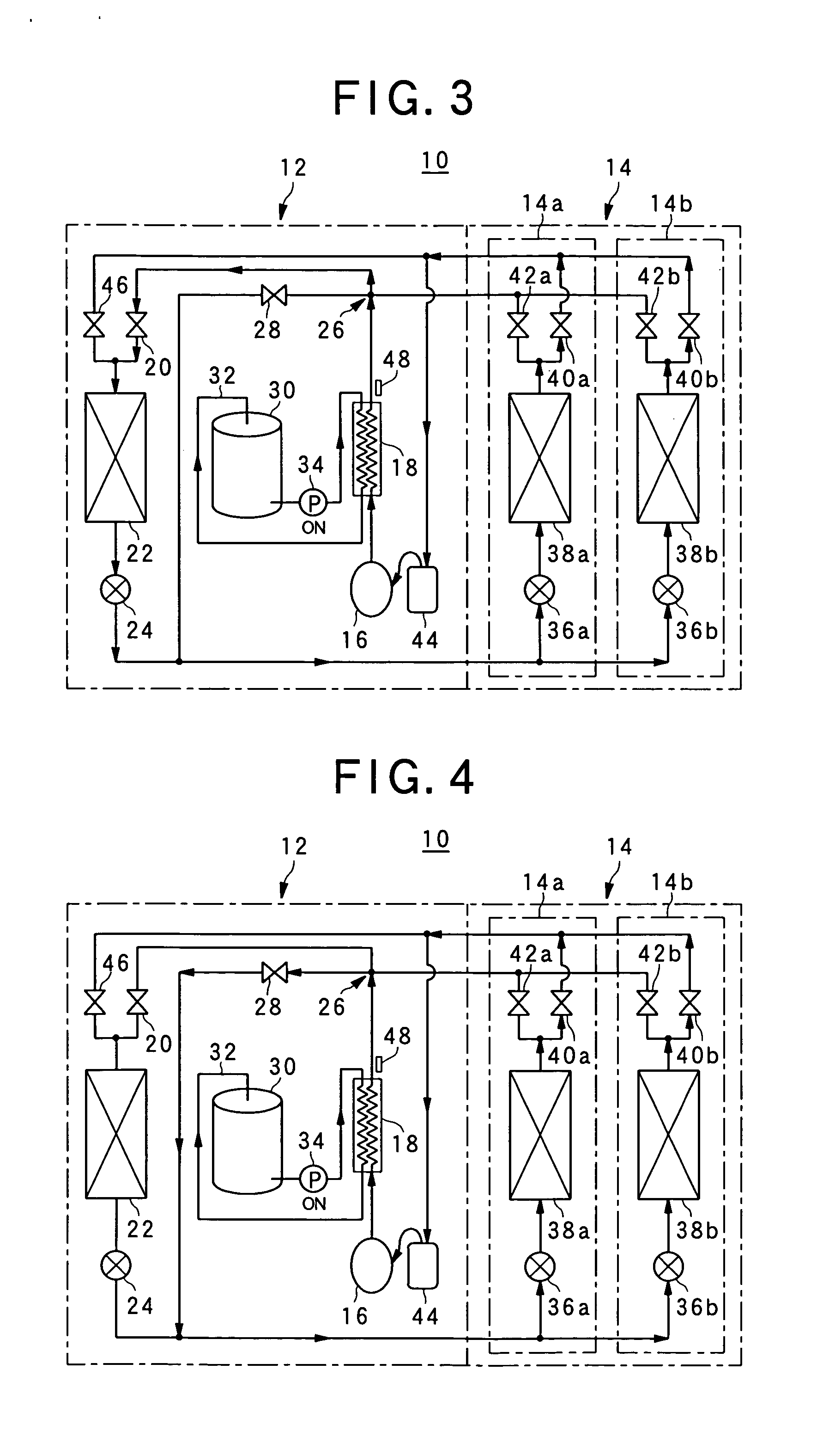
[0039] Under cooling operation, the first and second expansion valves 24, 36a, 36b are opened, the first and fourth electromagnetic valves 20, 40a, 40b are opened, and the second, third and fifth electromagnetic valves 46, 28, 42a and 42b are closed as shown in FIG. 3. The refrigerant discharged from the compressor 16 is once cooled in the gas cooler 18, and reaches the four-way branched passage 26. Here, since the third and the fifth electromagnetic valves 28, 42a and 42b are closed, the refrigerant flows to the first electromagnetic valve 20, and is further cooled and condensed in the outdoor heat exchanger 22. The refrigerant thus condensed flows from the first expansion valve 24 to the second expansion valves 36a and 36b because the third electromagnetic valve 28 is closed, and is evaporated in the indoor heat exchangers 38a and 38b. The evaporation of the refrigerant in the indoor heat exchangers 38a and 38b allows the user-side units 14a and 14b to car...

second embodiment

[0044] [Second Embodiment]

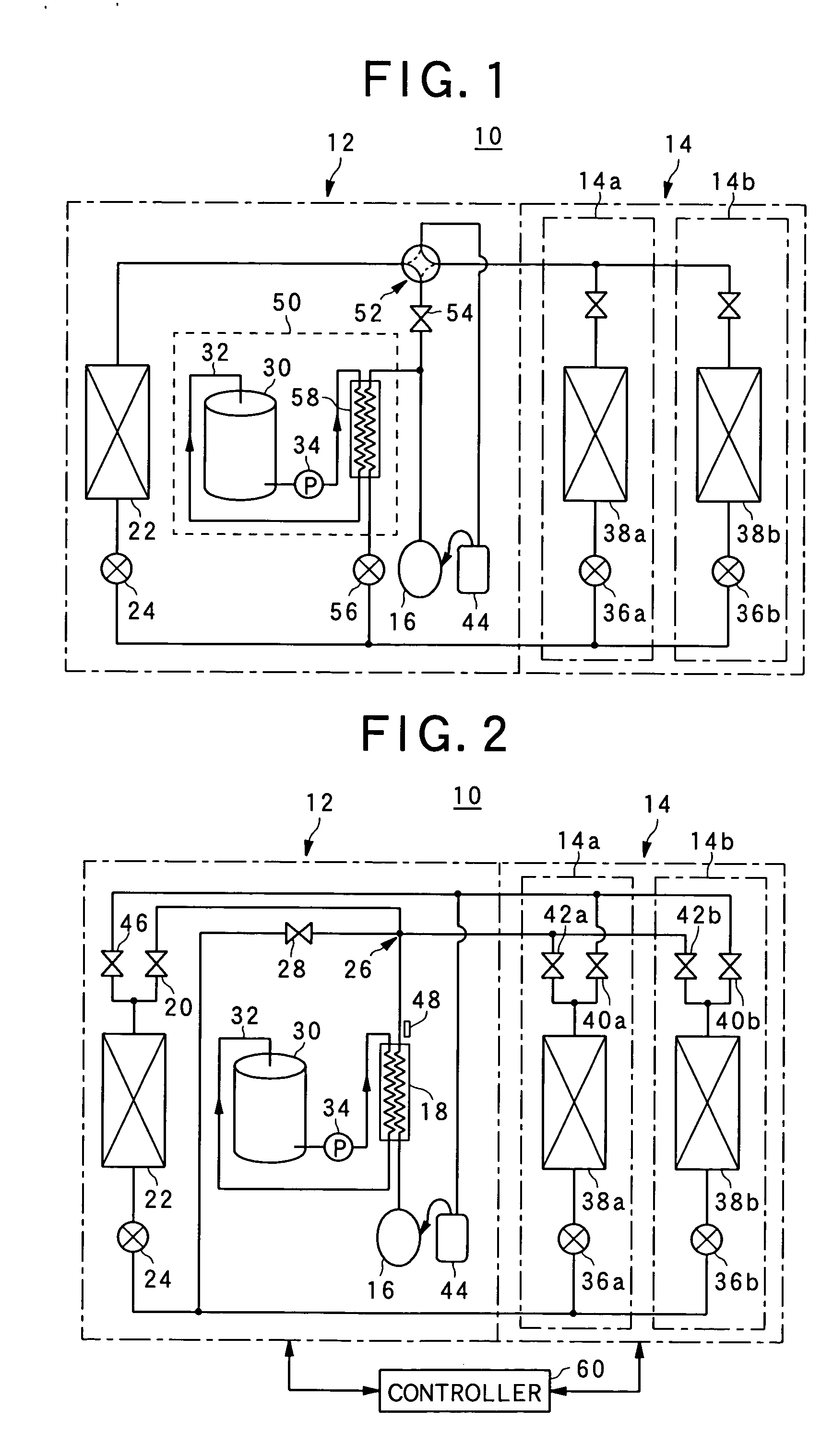
[0045] When the heating operation is carried out, as shown in FIG. 5, the first and second expansion valves 24, 36a, 36b are opened, the first, third and fourth electromagnetic valves 20, 28, 40a, 40b are closed, and the second and fifth electromagnetic valves 46, 42a, 42b are opened. In this case, the refrigerant discharged from the compressor 16 is passed through the gas cooler 18. Conversely to the cooling operation, the first and third electromagnetic valves 20 and 28 are closed, so that the refrigerant flows into the fifth electromagnetic valves 42a and 42b and then is condensed in the indoor heat exchangers 38a, 38b. The condensation of the refrigerant in the indoor heat exchangers 38a and 38b allow the user-side unit 14 to carry but the heating operation. When only one indoor unit is driven to carry out the heating operation, the fifth electromagnetic valve 42 of the indoor unit which is not driven is closed.

[0046] The refrigerant condensed in the i...

third embodiment

[0048] [Third Embodiment]

[0049] When only the hot water supply operation is needed, as shown in FIG. 6, the first expansion valve 24 is opened, the second expansion valves 36a and 36b are closed, the first and fifth electromagnetic valves 20, 42a and 42b are closed, the first and fifth electromagnetic valves 20, 421a, 42b are closed, and the second, third and fourth electromagnetic valves 46, 28, 40a, 40b are opened. Therefore, the refrigerant is circulated in the heat-source side unit 12, and thus no refrigerant flows in the user-side unit 14.

[0050] The refrigerant discharged from the compressor 16 is heat-exchanged with water in the gas cooler 18, and condensed therein. The refrigerant thus condensed reaches the four-way branch passage 26, and flows to the third electromagnetic valve 28 because the first and fifth electromagnetic valves 20, 42a and 42b are closed. Thereafter, the condensed refrigerant reaches the refrigerant pipe through which the first and second expansion valve...


PUM


Abstract

In a heat pump type hot water supply apparatus having a compressor (16), an outdoor heat exchanger (22), an expansion valve (24) and at least one indoor heat exchangers, and a water heat exchanger (18) for heat-exchanging refrigerant and water to achieve hot water, the water heat exchanger (18) is equipped in the refrigerant circuit so as to be connected to the outdoor heat exchanger (22) in series in the refrigerant circuit.

Description

BACKGROUND OF THE INVENTION [0001] 1. Field of the Invention [0002] The present invention relates to a heat pump type hot water supply apparatus, and particularly to a heat pump type hot water supply apparatus which can perform an air conditioning operation and a hot water supplying operation with energy saving. [0003] 2. Description of the Related Art [0004] A conventional heat pump type hot water supply apparatus is generally designed so that a heat exchanger of a hot water supply unit and an outdoor heat exchanger are arranged in parallel in a refrigerant circuit, and under cooling operation refrigerant circulating in the refrigerant circuit is cooled and condensed in both the heat exchanger of the hot water supply unit and the outdoor heat exchanger to cool the room. [0005]FIG. 1 shows a conventional heat pump type hot water supply apparatus 10 (disclosed in JP-A-10-288420, for example). The heat pump type hot water supply apparatus 10 shown in FIG. 1 contains an outdoor unit 12...

Claims


Application Information

Patent Timeline
Patent Type & Authority Applications(United States)
IPC IPC(8): F25B1/00F25B6/02F25B29/00F25B30/02
CPCF25B29/003F25B2700/21163F25B2339/047F25B2309/061
Inventor KAMIMURA, ICHIRO
Owner SANYO ELECTRIC CO LTD
Why Eureka
Try Eureka