Backlash preventing structure for steering column

a technology of steering column and backlash, which is applied in the direction of steering column, steering wheel parts, vehicle components, etc., can solve the problems of spoiling the manipulation feeling of the driver, degrading the rigidity of the steering wheel, and reducing the commercial value of the automobile itself, so as to prevent hammering noise, prevent backlash preventing structure for the steering column, and reduce the cost

Active Publication Date: 2005-03-31
FUJI KIKO CO LTD
View PDF7 Cites 28 Cited by
  • Summary
  • Abstract
  • Description
  • Claims
  • Application Information

AI Technical Summary

Benefits of technology

[0014] The present invention has been made in view of the problems mentioned above, and it is an object of the invention to provide a backlash preventing structure for a steering column which is capable of contributing to a reduction in cost with the employment of a less number of parts and to the ease of assembly, and is also capable of preventing hammering noise.
[0015] To achieve the above object, the present invention provides a backlash preventing structure for a steering column which has a cylindrical movable jacket slidably fitted into an outer cylindrical housing having three holes formed therethrough in an axial direction, a steering shaft swingably disposed within the movable jacket, and a steering wheel secured to one end of the steering shaft. The backlash preventing structure, which prevents backlash of the movable jacket against the outer cylindrical housing, includes a pair of press members each fitted into a left or a right side hole of the outer cylindrical housing, and a leaf spring fixed to the outer cylindrical housing with a screw screwed into a central hole of the outer cylindrical housing for urging the press members onto an outer peripheral surface of the movable jacket.
[0019] In the backlash preventing structure described above, the press members are directly urged by the leaf spring onto the outer peripheral surface of the movable jacket to effectively prevent backlash of the movable jacket against the outer cylindrical housing. This backlash preventing structure is composed of a total of four parts, i.e., two press members, one leaf spring, and one screw. In assembling these parts into the backlash preventing structure, the two press members are fitted into the associated holes, and covered with the leaf spring from above, and the leaf spring is fixed with the screw, thereby achieving a reduction in the number of parts, an improvement on the ease of assembly, and a resulting reduction in cost.
[0021] The leading end of the screw is fitted into the elongate hole formed through the movable jacket to prevent the movable jacket from rotating and to restrict the stroke thereof.

Problems solved by technology

However, in such a steering column, backlash in a telescopically movable structure would not only give unpleasant feeling to a driver who manipulates a steering wheel, but also cause a degradation in a steering wheel supporting rigidity, so that vibrations of the engine, vibrations of the chassis, when running on an irregular ground, and the like would cause the steering wheel to vibrate, thus spoiling manipulation feeling of the driver, and reducing the commercial value of the automobile itself.
However, since the foregoing backlash preventing structure requires a total of seven parts, i.e., one plate 103, two press members 107, one spring 105, one cover 106, and two screws 107, these parts cause an increase in cost.
Also, since the assembly of the backlash preventing structure involves mounting the two pressing members 104 with the spring 105 kept in a compressed state, dedicated assembling tools must be provided, thus implying a problem with respect to the ease of the assembly of the backlash preventing structure.

Method used


Image

  • Backlash preventing structure for steering column
  • Backlash preventing structure for steering column
  • Backlash preventing structure for steering column

Examples


Embodiment Construction

[0033] In the following, some embodiments of the present invention will be described with reference to the accompanying drawings.

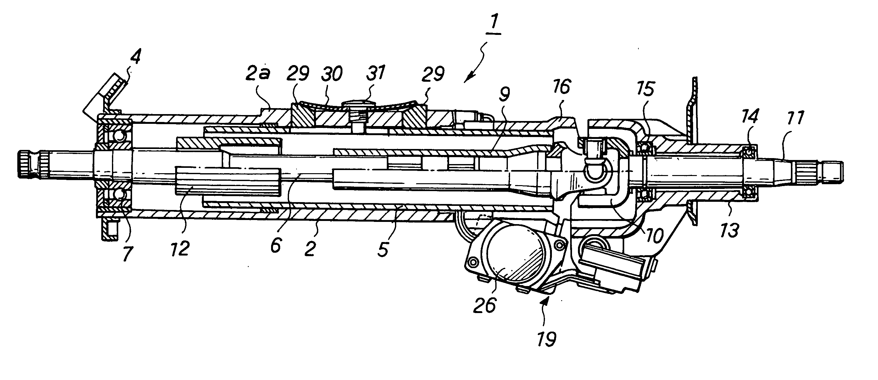
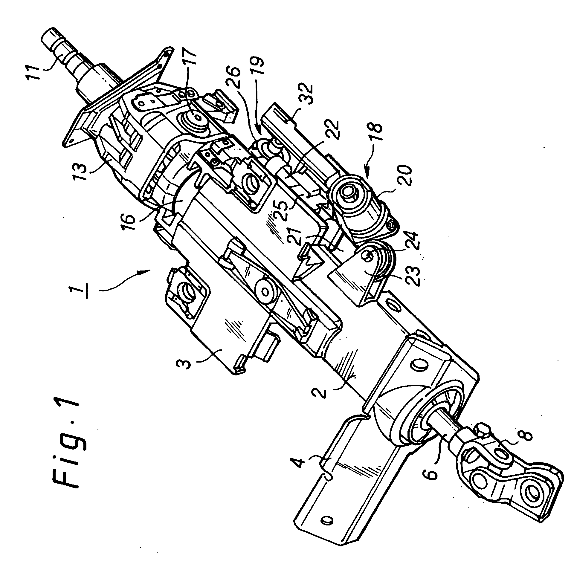
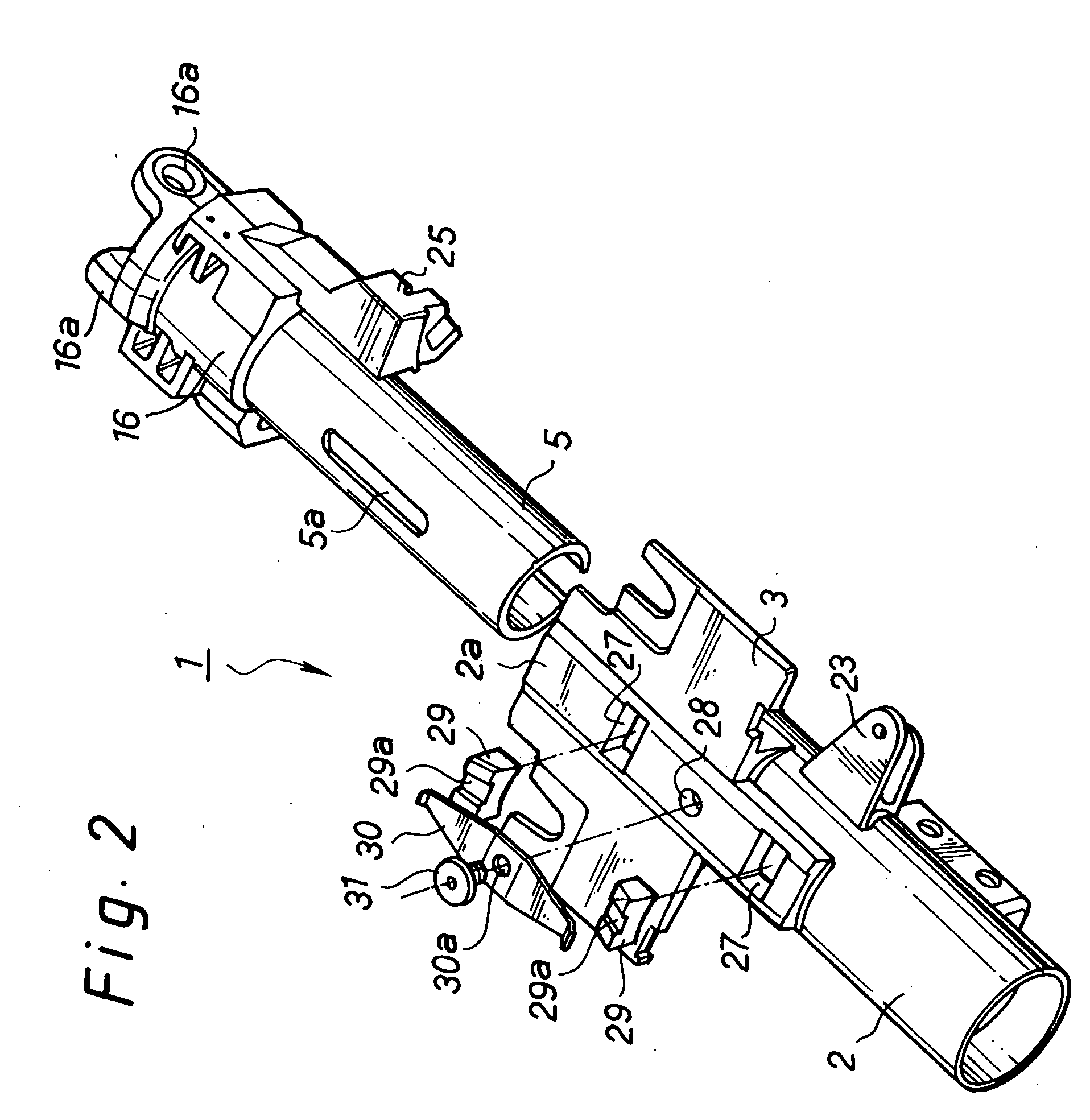
[0034]FIG. 1 is a perspective view of a steering column equipped with a backlash preventing structure according to one embodiment of the present invention, FIG. 2 is an exploded perspective view of the steering column, FIG. 3 is a longitudinal cross-sectional view, cut by half, for showing part of the steering column, FIG. 4 is a detailed cross-sectional view of the backlash preventing structure according to one embodiment of the present invention, FIG. 5 is a cross-sectional view taken along a line A-A in FIG. 4, and FIG. 6 is a cross-sectional view taken along a line B-B in FIG. 4.

[0035] A steering column 1 for use with a backlash preventing structure according to one embodiment of the present invention can permit a driver to adjust a steering wheel with a motor-driven mechanism by tilting the steering wheel in the vertical direction and / or moving up o...


PUM


Abstract

A backlash preventing structure for a steering column is provided for reducing the cost by reducing the number of parts and improving the ease of assembly, and for preventing hammering noise. The steering column has a cylindrical movable jacket slidably fitted into an outer cylindrical housing, the outer cylindrical housing having three holes formed therethrough in an axial direction, a steering shaft swingably disposed within the movable jacket, and a steering wheel secured to one end of the steering shaft. The backlash preventing structure, which prevents backlash of the movable jacket against the outer cylindrical housing, comprises a pair of press members each fitted into a left or a right side hole of the outer cylindrical housing, and a leaf spring fixed to the outer cylindrical housing with a screw screwed into a central hole of the outer cylindrical housing for urging the press members onto an outer peripheral surface of the movable jacket.

Description

BACKGROUND OF THE INVENTION [0001] 1. Field of the Invention [0002] The present invention relates to a backlash preventing structure for a steering column which is equipped in an automobile. [0003] 2. Description of the Related Art [0004] A steering column, which is a device for changing the direction in which an automobile runs, may permit a driver to adjust a steering wheel by tilting the steering wheel in the vertical direction and moving up or down the steering wheel along a steering shaft in order for the driver to ensure an optimal driving posture for his physical constitution. [0005] However, in such a steering column, backlash in a telescopically movable structure would not only give unpleasant feeling to a driver who manipulates a steering wheel, but also cause a degradation in a steering wheel supporting rigidity, so that vibrations of the engine, vibrations of the chassis, when running on an irregular ground, and the like would cause the steering wheel to vibrate, thus sp...

Claims


Application Information

Patent Timeline
Patent Type & Authority Applications(United States)
IPC IPC(8): B62D1/18B62D1/181B62D1/185B62D1/187
CPCB62D1/185B62D1/181
Inventor ARIHARA, KOUJI
Owner FUJI KIKO CO LTD
Why Eureka
Try Eureka