Boat dock bumper & dockline storage system

a dockline and bumper technology, applied in the direction of waterborne vessels, etc., can solve the problems of difficulty in removing mooring lines, and unsightly mooring lines, so as to prevent damage to cushion boats, easy to store mooring lines, and convenient grabbing of mooring lines

Inactive Publication Date: 2005-03-31
ALAN BRAD
View PDF2 Cites 5 Cited by
  • Summary
  • Abstract
  • Description
  • Claims
  • Application Information

AI Technical Summary

Benefits of technology

[0012] The mooring line freely passes through the slot and is not forced there through. Alternatively when flaps are utilized, the mooring line will pass through the deformed flaps into the interior hollow The mooring line simply lays in the interior hollow of the bumper and mooring line receptacle and is held substantially taught by an abutment member which is snappably engageable into the slot. Preferably, the abutment member is adjustably positionable on the mooring line to thereby be positioned to abut the far end of the bumper and mooring line receptacle when the mooring line is resident therein. A guide member at the near end of the bumper and mooring line receptacle can aid to guide the mooring line into the slot when the mooring line is being stored there inside. Alternatively the mooring line can be secured to a hardware member (eyebolt), which is affixed to the dock facility.
[0013] Accordingly, it is an object of the present invention to provide a bumper and m

Problems solved by technology

Problematically, when a skipper leaves dock, the mooring lines may be loosely placed on the dock facility, where after they may slide off and then dangle into the water.
Dangling mooring lines are, of course, unsightly, unsafe, and pose other problem on the dock facility.
On the other hand, if the mooring lines are secured to some component of the dock facility to prevent potentia

Method used


Image

  • Boat dock bumper & dockline storage system
  • Boat dock bumper & dockline storage system
  • Boat dock bumper & dockline storage system

Examples


Embodiment Construction

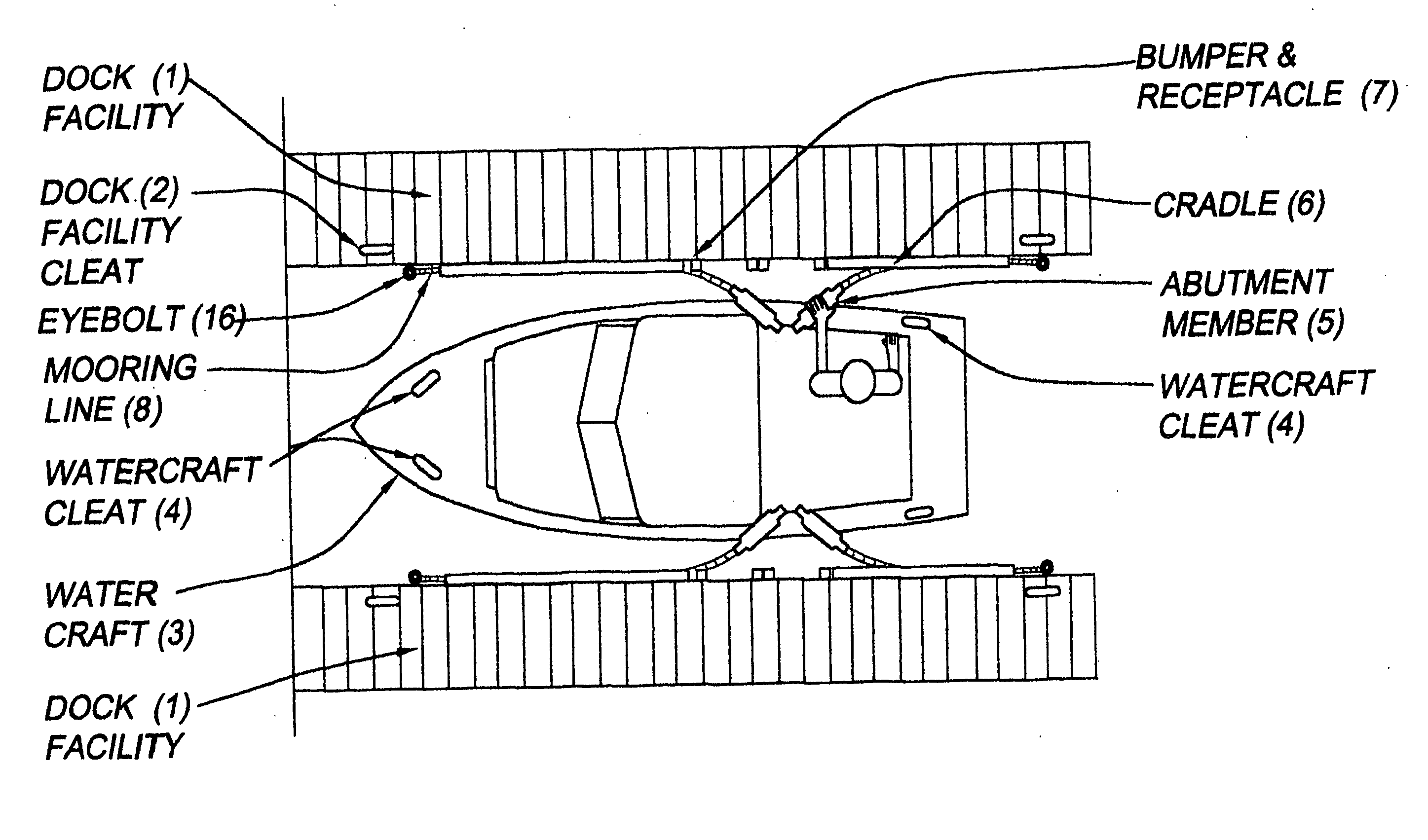
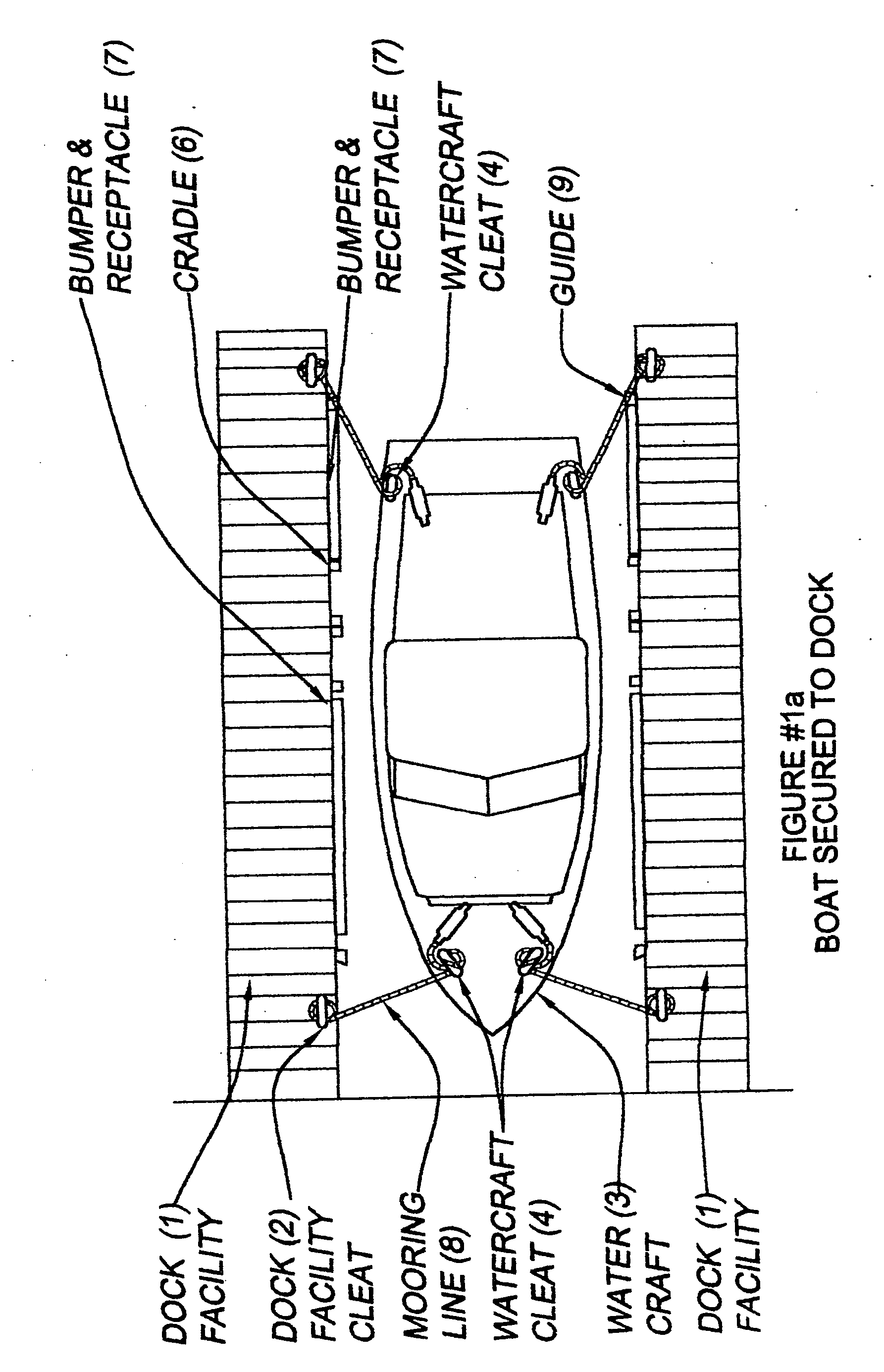
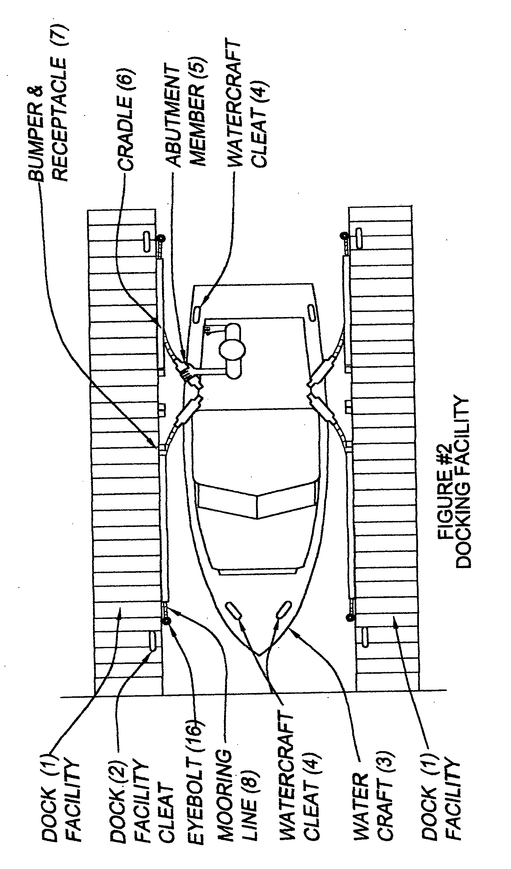
[0028] Referring now to the Drawing. FIG. 1 generally depicts the bumper and mooring line receptacle apparatus according to the present invention in operation with respect to a dock facility 1 and a watercraft 3, wherein a bumper and mooring line receptacle apparatus 7 is depicted by way of example. FIG. 3 depicts the bumper and mooring line receptacle apparatus 7, apparatus according to the present invention.

[0029] As shown by FIGS. 1, 1a, 2, 2a &5 the bumper and mooring line receptacle apparatus 7 for mooring line 8. The bumper and mooring line receptacle 7 is secured to the dock facility 1 thereof, preferably at a location with respect thereto which is adjacent the watercraft bumper 3a.

[0030] Preferably, the abutment member 5 shall be located on dock facility adjacent to the port and starboard sides of the watercraft 3 where the skipper and crew / passengers enter and leave the watercraft, generally aship of the watercraft. Each bumper and mooring line receptacle 7 has an interio...


PUM


Abstract

A bumper and mooring line receptacle apparatus for a dock facility includes an elongated bumper and mooring line receptacle for one or each mooring line, wherein each bumper and mooring line receptacle is connected with the dock facility; and further includes an abutment member connected with each mooring line at a distal end thereof. The bumper and mooring line receptacle has an interior hollow defined by a sidewall, having a slot therein along its entire length. The sidewall opposite the sot is attached to the sidewall of a selected dock facility via threaded fasteners or suitable. One bumper and mooring line receptacle can be located at the port bow, another at the starboard bow, another at the port stern and another at the starboard stern. Preferably, each of the sets of port and starboard bumper and mooring line receptacles end near each other at a generally amidship location on the gunwale where the skipper and crew/passengers enter and leave the watercraft. The mooring line is composed of conventional material used for nautical moorage, and has an abutment member at its distal end. The slot has a width either smaller than the cross-section of the mooring line such that the mooring line is forced through the slot into the interior hollow of the bumper and mooring line receptacle or is larger than the cross-section of the mooring line such that the mooring fine easily passes through the slot. Thereupon, the mooring line rests storingly in the interior hollow for storing the mooring line when not in use.

Description

CROSS REFERENCE TO RELATED APPLICATIONS [0001] Provisional Patent Application No. 60 / 506,970 Sep. 29, 2003 Confirmation #2282[0002] A bumper and mooring line receptacle apparatus for a dock facility includes an elongated bumper and mooring line receptacle for one or each mooring line, wherein each bumper and mooring line receptacle is connected with the dock facility, and further includes an abutment member connected with each mooring line at a distal end thereof. The bumper and mooring line receptacle has an interior hollow defined by a sidewall, having a slot therein along its entire length. The sidewall opposite the sot is attached to the sidewall of a selected dock facility via threaded fasteners or suitable. One bumper and mooring line receptacle can be located at the port bow, another at the starboard bow, another at the port stern and another at the starboard stern. Preferably, each of the sets of port and starboard bumper and mooring line receptacles end near each other at a...

Claims


Application Information

Patent Timeline
IPC IPC(8): B63B21/00
CPCB63B21/00
Inventor ALAN, BRAD
Owner ALAN BRAD
Why Eureka
Try Eureka