Paper handling apparatus

a paper handling and paper processing technology, applied in the field of paper handling apparatuses, can solve the problems of paper detection sensor failure to detect paper in time, excessive paper stacked on paper to be stapled, and following sheet affecting the accuracy of alignment performed in the processing tray

Active Publication Date: 2005-03-31
RICOH KK
View PDF36 Cites 61 Cited by
  • Summary
  • Abstract
  • Description
  • Claims
  • Application Information

AI Technical Summary

Benefits of technology

[0008] Accordingly, it is a general object of the present invention to provide a novel and useful paper handling apparatus in which at least one of the above problems is eliminated.

Problems solved by technology

If only a few pages are to be stapled, however, the paper detection sensor fails to detect the paper in time.
In such a case, excessive paper may be stacked on the paper to be stapled.
In addition, as the speed of printing of the image forming apparatus increases, the paper handling apparatus needs to handle the paper quickly enough so as not to keep the image forming apparatus waiting.
In addition, when a preceding sheet of paper that is set aside is re-transported, the deviation between the preceding sheet and a following sheet affects the accuracy of alignment performed in the processing tray.
When the paper transported at high speed is stopped in a short time, the paper may not stop at a desired position.

Method used


Image

  • Paper handling apparatus
  • Paper handling apparatus
  • Paper handling apparatus

Examples


1st embodiment

1st Embodiment

[0038]

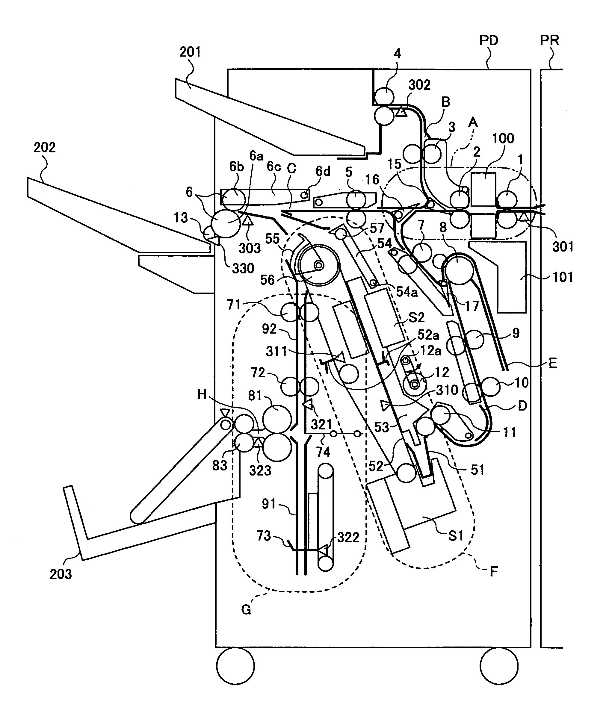
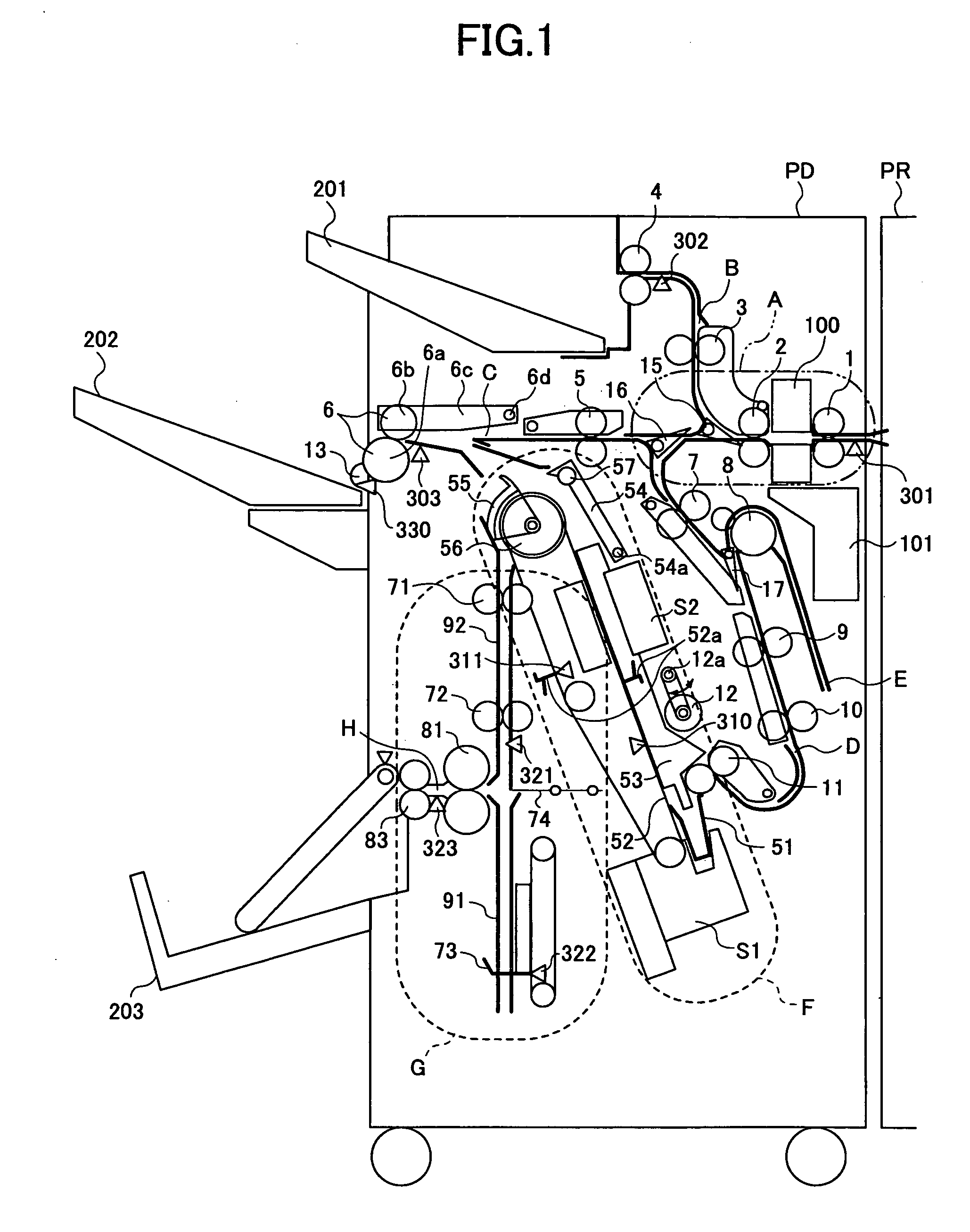
[0039]FIG. 1 is a cross section of an image forming system including a paper handling apparatus according to an embodiment and an image forming apparatus. As shown in FIG. 1, the entire cross section of the paper handling apparatus is shown, but only a portion of the image forming apparatus is shown.

[0040] As shown in FIG. 1, the paper handling apparatus PD is provided at the side of the image forming apparatus PR. The paper discharged from the image forming apparatus PR is guided to the paper handling apparatus PD. Each sheet of paper is transported through a path A having a post-processing unit. The post-processing unit includes, but is not limited to, a punch unit 100, for example, that punches the sheet of paper. After passing through the path A, the sheet of paper is directed to either a path B, a path C, or a path D by branching nails 15 and 16. The sheet of paper directed to the path B is directly discharged onto a upper tray 201 via transportation roller...

2nd embodiment

2nd Embodiment

[0091]FIG. 12 is a schematic diagram for explaining the operation of a paper handling apparatus according to the second embodiment of the present invention. FIGS. 13 through 16 are schematic diagrams for explaining the pre-stacking operation of the paper handling apparatus according to the second embodiment in which the paper is set aside in the pre-stacking path E and re-transported. Elements identical to those of the paper handling apparatus according to the first embodiment are referred to by the same reference symbols, and their description is omitted.

[0092] As shown in FIG. 12, the paper handling apparatus PD according to the present embodiment is different from that of the first embodiment shown in FIG. 3 in that the transportation roller R3 is removed and the transportation roller R4 functions as the transportation rollers R3 and R4 of the first embodiment.

[0093] If the transportation roller R3 is removed, the paper cannot be reversely transported to a positio...

3rd embodiment

3rd Embodiment

[0098] In the case of the second embodiment, when the sheet P1 is in the set-aside state, the sheet P1 is not nipped by the transportation roller R4. While the sheet P1 is in the set-aside state, the sheet P1 may remain nipped by the transportation roller R4 in the third embodiment.

[0099] In the set-aside state, the sheet P1 is nipped by the transportation roller R4 with its front end protruding from the transportation roller R4 to the downstream direction. When the following sheet P2 comes to the nip of the transportation roller R4, the two sheets P1 and P2 are transported together as shown in FIGS. 15 and 16. The front end of the preceding sheet P1 is ahead of the front end of the following sheet P2 by a predetermined distance. In the case of the second embodiment, the sheet P1 is positioned at the nip of the transportation roller R4 by gravity. It would be possible for the set-aside paper to accidentally fail to be nipped again by the transportation roller R4. Acco...


PUM

PropertyMeasurementUnit
distanceaaaaaaaaaa
lengthaaaaaaaaaa
thicknessaaaaaaaaaa

Abstract

A paper handling apparatus is disclosed, having a first path that guides paper to a processing tray; a second path in which the paper is set aside; and a transportation unit that transports the paper. The paper handling apparatus sets aside a preceding sheet of the paper in the second path, and transports the set-aside preceding sheet of the paper with a following sheet of the paper. The paper handling unit includes: a branching unit that, when the paper is transported in the second direction, leads the paper to the second path; a paper detection unit provided in a more upstream position than the branching unit; and a control unit that determines timing in which the paper is transported in the second direction based on an output of the paper detection unit, and causes the transportation unit to transport the paper to the second path.

Description

BACKGROUND OF THE INVENTION [0001] 1. Field of the Invention [0002] The present invention generally relates to a paper handling apparatus, and more particularly, to a paper handling apparatus coupled to an image forming apparatus for sorting, stapling, and stacking papers discharged from the image forming apparatus. [0003] 2. Description of the Related Art [0004] Many kinds of paper handling apparatuses coupled to an image forming apparatus for sorting, stapling, and stacking papers discharged from the image forming apparatus are known in the art. Japanese Laid-Open Patent Applications No. 8-301508 and 9-235069, for example, disclose a paper handling apparatus that can buffer the paper so that the image forming apparatus does not need to wait for the paper handling apparatus to complete the handling of paper. [0005] The paper handling apparatus needs to control the number of buffered sheets, for example, since the printing speed, the number of copies, and processing mode of the imag...

Claims


Application Information

Patent Timeline
Patent Type & Authority Applications(United States)
IPC IPC(8): B65H29/58G03G15/00B65H29/60B65H31/32B65H39/10
CPCB65H29/60B65H39/10B65H2301/4213B65H2404/632B65H2511/51B65H2513/41B65H2513/51B65H2801/06B65H2220/01B65H2220/02
Inventor IIDA, JUNICHIOKADA, HIROKITOKITA, JUNICHIYAMADA, KENJISAITOH, HIROMOTONAGASAKO, SHUUYAKIKKAWA, NAOHIRO
Owner RICOH KK
Why Eureka
Try Eureka