Cell unit and power supply control method

Inactive Publication Date: 2005-03-31
KK TOSHIBA
View PDF9 Cites 21 Cited by
  • Summary
  • Abstract
  • Description
  • Claims
  • Application Information

AI Technical Summary

Benefits of technology

[0011] Embodiments of the present invention may provide a cell unit and power su

Problems solved by technology

For example, the electronic device may consume power more than the rated output of the DMFC.
In some cases, a

Method used


Image

  • Cell unit and power supply control method
  • Cell unit and power supply control method
  • Cell unit and power supply control method

Examples


Embodiment Construction

[0029] Embodiments of the present invention will be described below with reference to the drawings.

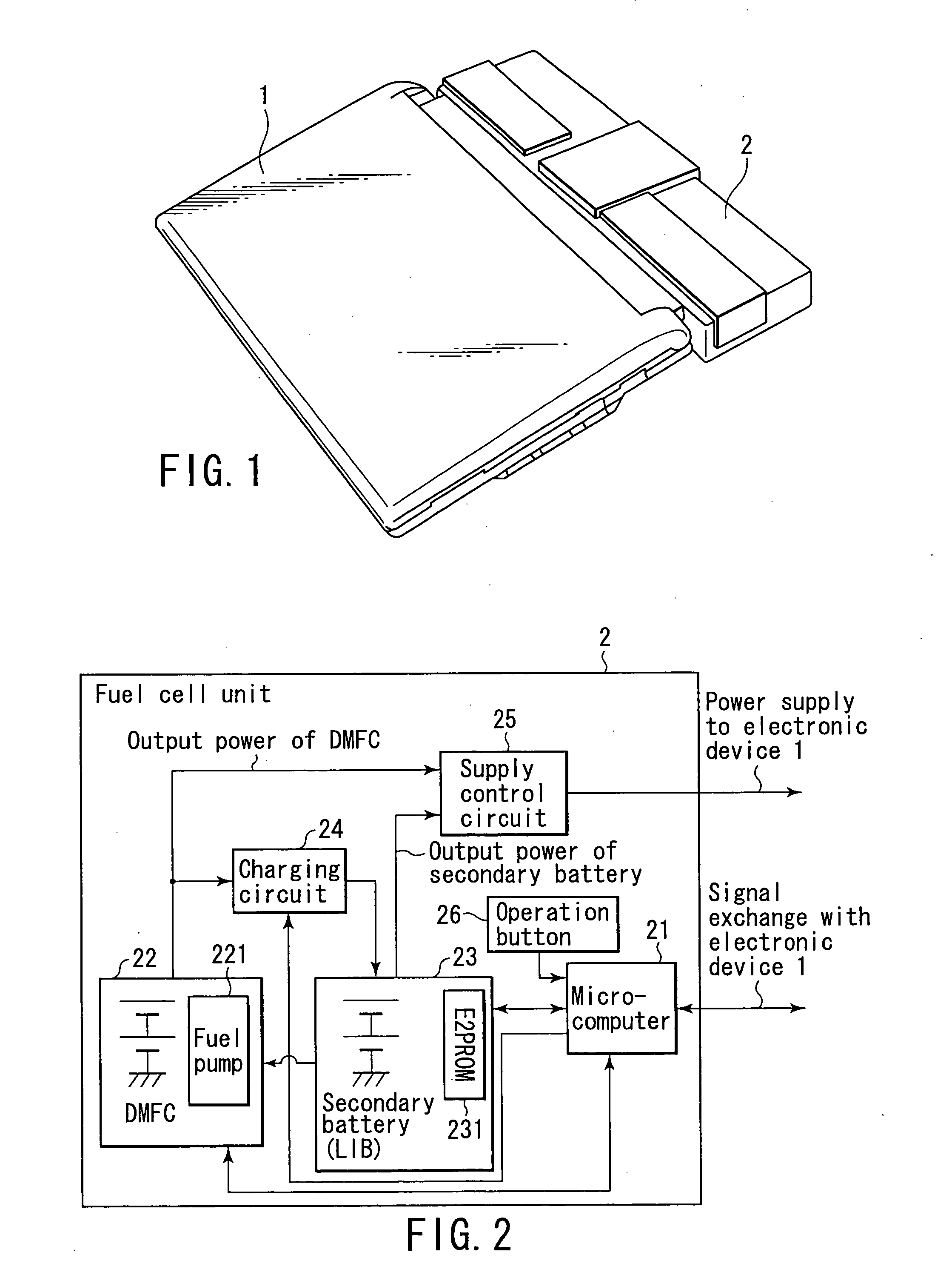
[0030]FIG. 1 is a perspective view showing the outer appearance of an electronic device system according to the embodiment of the present invention.

[0031] As shown in FIG. 1, the electronic device system according to the embodiment includes an electronic device 1, and a fuel cell unit 2 freely detachable from the electronic device 1. The electronic device 1 is, e.g., a notebook personal computer in which a lid having an LCD (Liquid Crystal Display) on its inner surface is attached to the main body by a hinge mechanism so as to be freely openable / closable. The electronic device 1 can operate by power supplied from the fuel cell unit 2. The fuel cell unit 2 incorporates a DMFC capable of generating power by a chemical reaction, and a secondary battery capable of being repetitively charged and discharged.

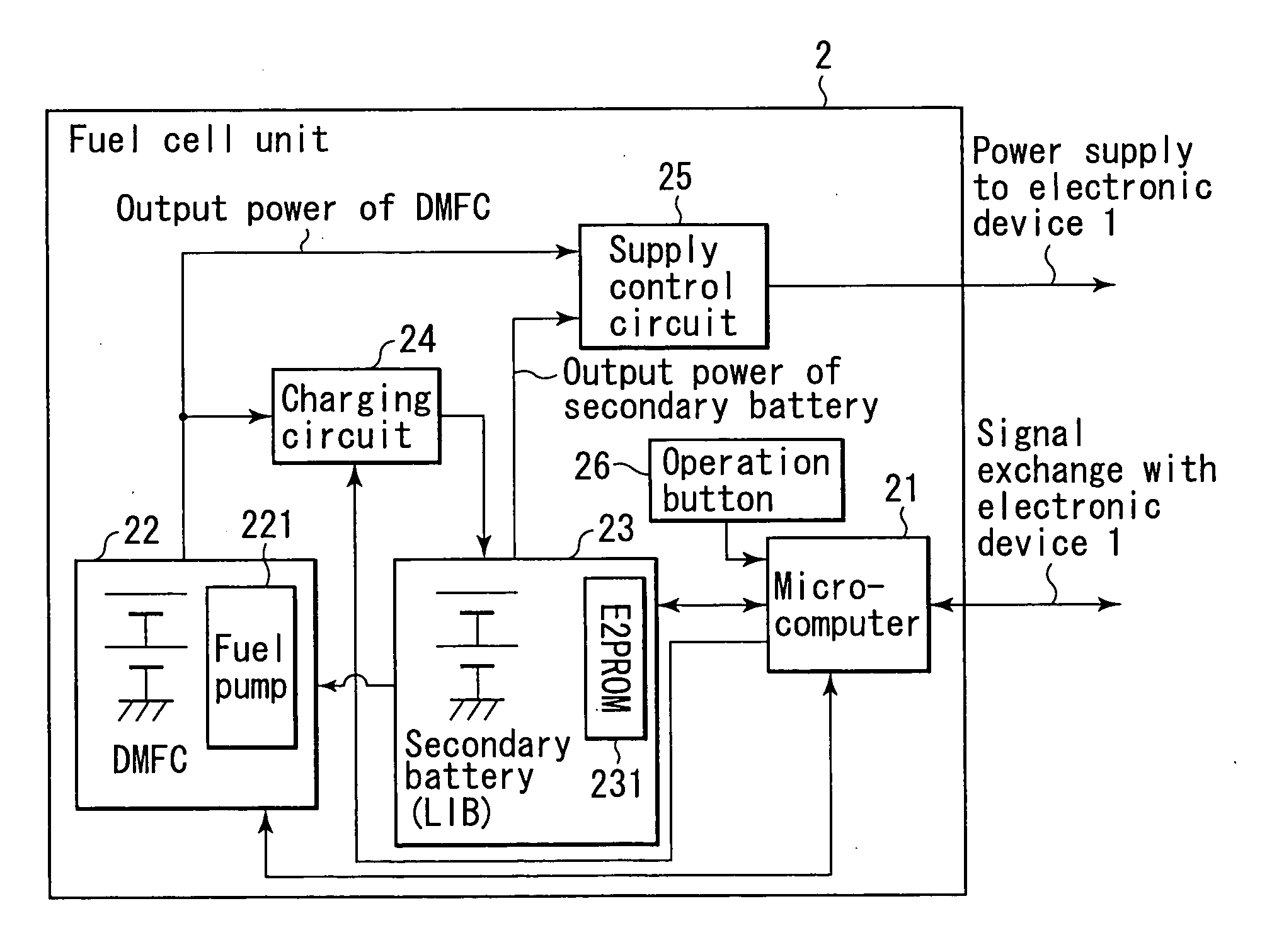
[0032]FIG. 2 is a block diagram showing the schematic arrangement of the fuel cell...


PUM


Abstract

A cell unit includes a fuel cell capable of generating power by a chemical reaction, a secondary battery capable of being repetitively charged and discharged, a DC/DC converter which DC/DC-converts power output from the fuel cell and outputs power, the DC/DC converter monitoring an output voltage of a cell in the fuel cell and dropping an output voltage of the DC/DC converter when the monitored output voltage of the cell reaches not more than a predetermined value, and a diode OR circuit which selectively acquires power according to a load to which the power is supplied, from power output from the DC/DC converter and power output from the secondary battery, and outputs the acquired power.

Description

CROSS-REFERENCE TO RELATED APPLICATIONS [0001] This application is based upon and claims the benefit of priority from prior Japanese Patent Application No. 2003-307590, filed Aug. 29, 2003, the entire contents of which are incorporated herein by reference. BACKGROUND OF THE INVENTION [0002] 1. Field of the Invention [0003] The present invention relates to a cell unit having, e.g., a direct methanol type fuel cell, and a power supply control method. [0004] 2. Description of the Related Art [0005] In recent years, various battery-driven portable electronic devices such as a portable information terminal (e.g., called a PDA: Personal Digital Assistant) and a digital camera have been developed and are widely spread. [0006] Recently, environmental issues receive a great deal of attention, and environmentally friendly batteries have also actively been developed. A well-known battery of this type is a direct methanol fuel cell (to be referred to as a DMFC hereinafter). [0007] The DMFC caus...

Claims


Application Information

Patent Timeline
IPC IPC(8): H01M8/00H01M8/04H02J7/00H01M10/44H02J7/34
CPCH01M8/04552Y02E60/50H01M8/04582H01M8/04589H01M8/04873H01M8/0488H01M8/04932H01M8/0494H01M8/04947H01M8/04955H01M8/1011H01M10/0525H01M16/006H02J7/34H02J2001/004H01M8/04559H02J2300/30Y02E60/10
Inventor OZEKI, AKIHIRO
Owner KK TOSHIBA
Why Eureka
Try Eureka