Differential spin valve sensor having both pinned and self-pinned structures

a technology of differential spin valve and self-pinned structure, which is applied in the direction of magnetic recording, magnetic recording head, instruments, etc., can solve the problem that the setting process of 180° out-of-phase pinned structure becomes difficult for these types of sensors, and achieves the effect of higher read resolution

Inactive Publication Date: 2005-03-31
HITACHI GLOBAL STORAGE TECH NETHERLANDS BV
View PDF14 Cites 71 Cited by
  • Summary
  • Abstract
  • Description
  • Claims
  • Application Information

AI Technical Summary

Benefits of technology

[0013] It is a principal object to provide a dual / differential giant magnetoresistive (GMR) sensor which yields signals of opposite polarity under common mode excitation, thereby resulting in rejection of common mode noise and providing a higher read resolution. The dual / differential sensor includes first and second spin valve structures which are separated by a nonmagnetic gap layer. Each one of the spin valve structures includes first and second thin film layer structures of ferromagnetic (FM) material separated by a thin film layer of nonmagnetic material. The direction of magnetism in the first layer structure is free to rotate in response to an applied external magnetic field (the “free layer structure”). The direction of magnetism in the second layer structure is maintained in a fixed or pinned position and does not rotate when an external field is applied to the sensor (the “pinned layer structure”). By providing a sense current flow through the sensor, variations can be sensed in the resistivity of the sensor in response to an external magnetic field due to rotation of the magnetization in the free layer structure of ferromagnetic material.

Problems solved by technology

Unfortunately, the AFM setting process to establish 180° out-of-phase pinned structures becomes difficult for these types of sensors.

Method used


Image

  • Differential spin valve sensor having both pinned and self-pinned structures
  • Differential spin valve sensor having both pinned and self-pinned structures
  • Differential spin valve sensor having both pinned and self-pinned structures

Examples


first embodiment

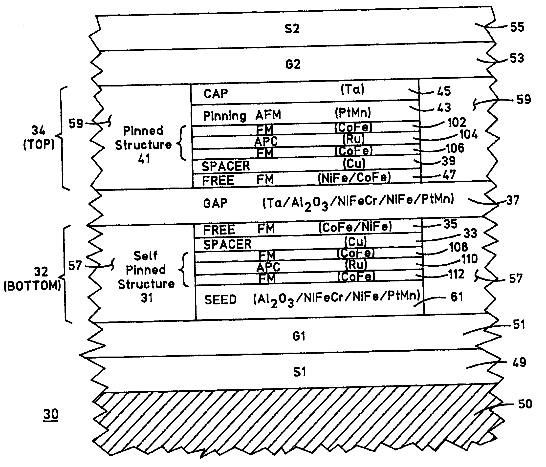
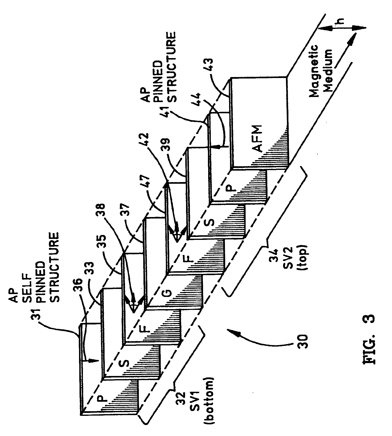
[0029] Referring now to FIG. 3, a dual / differential spin valve sensor 30 according to the present invention is shown. Sensor 30 includes first and second spin valve structures 32, 34 formed on a substrate and separated from each other by a thin layer of insulating gap material 37. Each spin valve structure 32, 34 has a first or “free” ferromagnetic (FM) layer 35, 47 separated by a thin nonmagnetic spacer layer 33, 39 from a second or “pinned” ferromagnetic (FM) layer 31, 41 in which the magnetization direction is fixed. Although not shown in detail in FIG. 3, each pinned layer 31 and 41 is actually a pinned layer structure which includes first and second FM layers with an antiparallel coupling (APC) layer sandwiched therebetween. A layer 43 of antiferromagnetic (AFM) material is deposited adjacent and in contact with pinned layer structure 41 to fix (i.e. pin) the magnetization direction in the pinned layer by exchange coupling. On the other hand, pinned layer structure 31 has a mag...

second embodiment

[0038]FIG. 5 is an ABS view of dual / differential spin valve sensor 30 in a Sensor 30 is similar to that shown and described in relation to FIGS. 3-4, except that pinned layer structure 41 (being exchanged-coupled) is provided in bottom spin valve structure 32 and pinned layer structure 31 (being self-pinned) is provided in top spin valve structure 34. Thus, pinning layer 43 is provided adjacent to pinned layer structure 41 (i.e. FM layer 106) over seed layer 61 in bottom structure 32, and no pinning layer is required in top structure 34. Seed layer 61 no longer needs the thin PtMn layer (compare seed layer 61 of FIG. 4) but may be formed simply as Al2O3 / NiFeCr / NiFe.

[0039] Dual / differential spin valve sensors are advantageous as they yield signals of opposite polarity under common mode excitation, thereby resulting in rejection of common mode noise and providing a higher read resolution determined by the gap layer which separates the two spin valve structures. Conventionally, the tw...


PUM

PropertyMeasurementUnit
thickaaaaaaaaaa
thicknessaaaaaaaaaa
non-magnetic electrically conductiveaaaaaaaaaa

Abstract

A dual / differential spin valve sensor of a magnetic head includes a first spin valve having an antiparallel (AP) “pinned” layer structure and a second spin valve having an AP “self-pinned” layer structure. The AP pinned layer structure has a magnetization direction which is fixed by an adjacent antiferromagnetic (AFM) layer, whereas the AP self-pinned layer structure has a magnetization direction which is fixed by magnetostriction as well as air bearing surface (ABS) stress. The magnetization direction of the AP pinned layer structure is fixed in a direction antiparallel to the magnetization direction of the AP self-pinned layer structure. The dual / differential spin valve sensor may be configured to have either a top AP pinned layer structure and a bottom AP self-pinned layer structure, or a top AP self-pinned layer structure and a bottom AP pinned layer structure. Advantageously, the dual / differential spin valve sensor is relatively thin and overcomes the difficulties of the AFM polarity setting process when two AP pinned layer structures are utilized.

Description

BACKGROUND OF THE INVENTION [0001] 1. Field of the Invention [0002] This invention relates generally to spin valve sensors of magnetic heads, and more particularly to a differential spin valve sensor utilizing both an antiparallel (AP) pinned layer structure and an AP self-pinned layer structure. [0003] 2. Description of the Related Art [0004] Computers often include auxiliary memory storage devices having media on which data can be written and from which data can be read for later use. A direct access storage device (disk drive) incorporating rotating magnetic disks are commonly used for storing data in magnetic form on the disk surfaces. Data is recorded on concentric, radially spaced tracks on the disk surfaces. Magnetic heads including read sensors are then used to read data from the tracks on the disk surfaces. [0005] In high capacity disk drives, magnetoresistive read (MR) sensors, commonly referred to as MR heads, are the prevailing read sensors because of their capability to...

Claims


Application Information

Patent Timeline
Patent Type & Authority Applications(United States)
IPC IPC(8): G11B5/33
CPCG11B5/33
Inventor GILL, HARDAYAL SINGH
Owner HITACHI GLOBAL STORAGE TECH NETHERLANDS BV
Why Eureka
Try Eureka