Spacial derivative bus encoder and decoder

a derivative bus and encoder technology, applied in the field of electronic data transmission methods and apparatuses, can solve problems such as masking or exaggerating voltage level variations, affecting the accuracy of transmission errors, so as to reduce inter-symbol interference and reduce base line wander

Inactive Publication Date: 2007-01-23
MORGAN STANLEY +1
View PDF53 Cites 70 Cited by
  • Summary
  • Abstract
  • Description
  • Claims
  • Application Information

AI Technical Summary

Benefits of technology

[0009]The embodiments of the present invention are improvements over conventional systems and methods in part because fewer transmission lines are required and as a result noise generated at the transmitter circuit is reduced. Conventional differential transmission systems use 2*n lines for n bits, where the system of the invention requires only n+1 lines. In addition, power consumed by the transmitter circuit is decreased because fewer signals have to be transmitted. The reduced number of required lines allows devices employing the system and methods of the invention to maintain high quality data transmission while reducing the costs associated with manufacturing and maintaining more transmission lines. Another advantage of the present invention is that common mode noise is removed at the receiver. In one embodiment the system of the invention also compensates for crosstalk between the signals.
[0010]According to one embodiment of the invention, a method of encoding n signals is provided, using a reference voltage signal, wherein the differences between adjacent signals are determined and transmitted as n+1 encoded signals. A method of decoding m encoded signals is also provided, wherein the encoded signals are processed through an array of resistors, giving the original n signals.
[0011]Another embodiment describes a spacial derivative encoder, comprising one or more differential amplifiers, including a first and a second differential amplifier, one or more input data lines connected to the one or more differential amplifiers, a fixed reference voltage line, connected to the first and the second differential amplifier, and one or more output transmission lines connected to the one or more differential amplifiers, the number of output transmission lines equal to n+1, where n is the number of input data lines. A spacial derivative decoder is also provided, comprising one or more input transmission lines, one or more differential amplifiers, the number of differential amplifiers equal to m−1, where m is the number of encoded input transmission lines, a resistor network electrically located between the one or more input transmission lines and the one or more differential amplifiers, and one or more output data lines connected to the one ore more differential amplifiers, the number of output data lines equal to the number of differential amplifiers. In an additional embodiment the resistor network further comprises an array of resistors for averaging signals received on the one or more input transmission lines. Yet another embodiment provides a communications system, comprising a spacial derivative encoder and a spacial derivative decoder.
[0012]In another embodiment, signals are processed through a time-domain encoding scheme prior to differential encoding. This allows the system to account for the actual variation of a signal voltage, thereby compensating for signal dispersion and reducing base line wander due to frequency-dependent attenuation on lines. Time-domain encoding also reduces inter-symbol interference resulting from reflections or dispersion on the signal lines.

Problems solved by technology

Noise, interference, or other events such as ground voltage shifts between transmitter and receiver alter the signal such that what is sent may not be what is received.
One problem with this method is that it is not precise—the margin of error inherent in measuring voltage levels at the receiver may either mask or exaggerate voltage level variations due to noise.
In addition, since there is no signal being driven down the ground line, the ground line voltage may be affected differently by the interfering source, again potentially masking or exaggerating transmission errors.
The weakness is that it doubles the number of required transmission lines.

Method used


Image

  • Spacial derivative bus encoder and decoder
  • Spacial derivative bus encoder and decoder
  • Spacial derivative bus encoder and decoder

Examples


Embodiment Construction

[0019]In the following Detailed Description of the Preferred Embodiments, reference is made to the accompanying drawings which form a part hereof, and in which is shown by way of illustration specific embodiments in which the invention may be practiced. It is to be understood that other embodiments may be utilized and structural changes may be made without departing from the scope of the present invention.

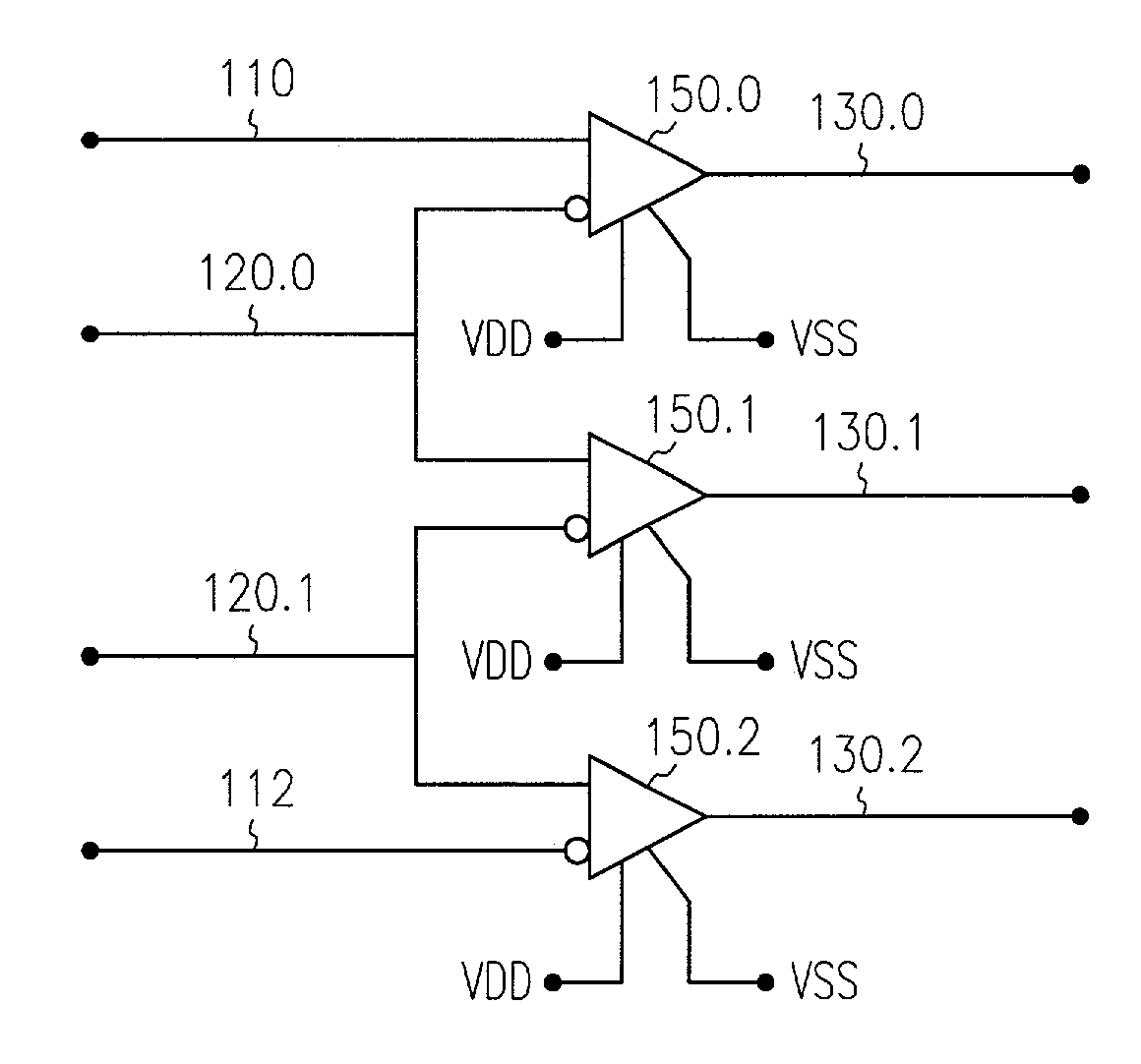
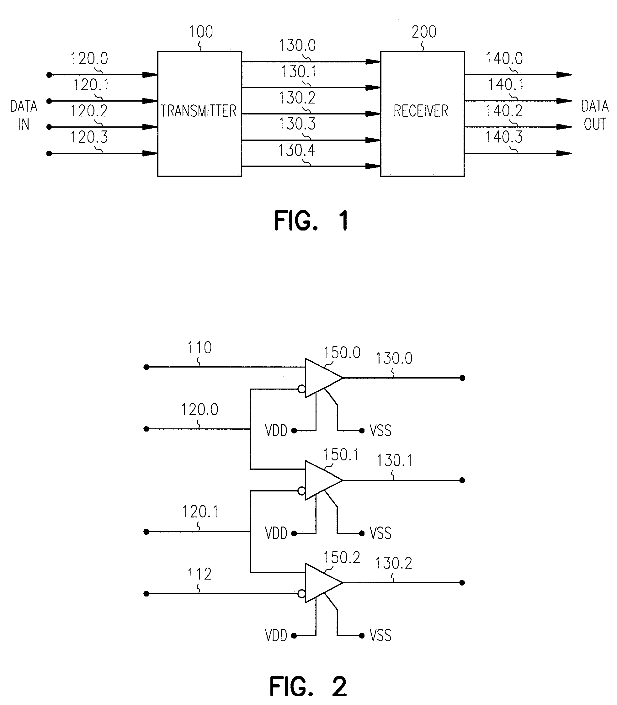
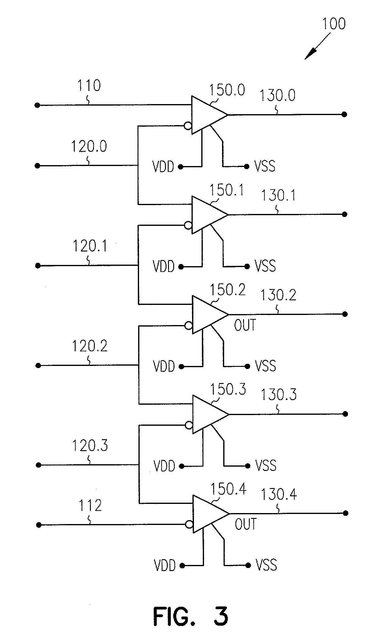
[0020]FIG. 1 is a block diagram of the basic process involved in transmitting data across a network. Input data is transferred to transmitter 100 from where it is then transmitted over one or more signal lines 130.0–130.4 to receiver 200. Receiver 200 then transfers the data out. An accurate data transmission system outputs data from receiver 200 which matches that input into transmitter 100. In one embodiment of the present invention data verification is accomplished through encoding the input data at transmitter 100 and then transmitting the encoded data to receiver 200 where it ...


PUM


Abstract

A method and apparatus for providing efficient and accurate electronic data transmission of information on a data bus in the presence of noise. Data signals are received on a plurality of input lines by a spacial derivative encoder. The spacial derivative encoder encodes the signals and transmits them to a receiver having a spacial derivative decoder. The spacial derivative decoder then decodes the signals. Minimal overhead is required as for n input lines only n+1 lines are needed to transmit each of the encoded signals.

Description

RELATED APPLICATIONS[0001]This application is a continuation application of Ser. No. 08 / 971,185, filed on Nov. 17, 1997 now U.S. Pat. No. 6,480,548, entitled SPACIAL DERIVATIVE BUS ENCODER AND DECODER.BACKGROUND OF THE INVENTION[0002]1. Field of the Invention[0003]The present invention relates in general to methods and apparatus for electronic data transmission, and in particular to a system and method for efficiently and accurately transmitting information on a data bus in the presence of noise.[0004]2. Background Information[0005]A data bus commonly consists of lines for transferring data words between devices within a computer. A data word is made up of data bits transmitted as varying voltages on the data bus lines. Noise, interference, or other events such as ground voltage shifts between transmitter and receiver alter the signal such that what is sent may not be what is received. The possibility of signal alteration, whether or not it actually occurs, creates a need for ways t...

Claims


Application Information

Patent Timeline
Patent Type & Authority Patents(United States)
IPC IPC(8): H04B14/04H03K5/22H04B3/54H04L25/14
CPCH04B3/548H04L25/14H04B2203/547H04B2203/5425
Inventor MANSUR, DANIEL C.
Owner MORGAN STANLEY
Why Eureka
Try Eureka